Maximum reaction rate converter system for exothermic reactions

a converter system and reaction rate technology, applied in the direction of physical/chemical process catalysts, bulk chemical production, metal/metal-oxide/metal-hydroxide catalysts, etc., can solve the problems of poor production rate, unusable by-product production, deactivation of catalysts, etc., and achieve the effect of increasing conversion and reducing catalyst volum

Active Publication Date: 2006-05-11
KELLOGG BROWN & ROOT LLC
View PDF55 Cites 31 Cited by
  • Summary
  • Abstract
  • Description
  • Claims
  • Application Information

AI Technical Summary

Benefits of technology

[0013] The present invention is directed to a conversion process and apparatus for synthesis of ammonia, for example, wherein reaction temperature along the length of the reactor can be controlled, resulting in decreased catalyst volumes and increased conversion. The reaction temperature can be reduced along the length of the reactor, to follow the equilibrium curve for the desired product such that the product concentration increases along the length of the reactor but never reaches the equilibrium product concentration at the current reaction mixture temperature.

Problems solved by technology

Negative effects can include: poor production rates, deactivation of catalyst, production of unwanted by-products, and damage to the reaction vessel and piping.
Most commonly, an excessive temperature increase in the reaction zone either limits selectivity or reduces product yield.
Thus, higher reaction temperatures generally result in faster reaction rates and lower overall conversion, while lower reaction temperatures generally result in slower reaction rates and higher overall conversion.
However, because the reaction is done in stages with interstage cooling, the equilibrium and kinetics are rarely, or only for very briefly, balanced for the maximum reaction rate possible.
The geometry of intercooled reactors poses layout constraints that require large reactors and vast tube surfaces to achieve high heat transfer efficiencies.
While overall catalyst efficiency can be better than is found in reactors operating at adiabatic conditions, of course, the isothermal condition means that towards the outlet of the reactor, the reaction composition may still approach equilibrium product concentrations, thus limiting further reaction.
In practice, prior art reaction processes have been limited to two to four stages in one common reactor vessel, with the major limitation being the capital costs associated with interstage heat exchange equipment and multiple reactor stages and / or vessels.
The exothermic nature of the reaction, together with the adiabatic reactor bed design, do not allow the temperature profile to maximize per-pass ammonia conversion, in turn leading to inefficient catalyst use.
Similarly, isothermal reactors have limitations in the production of ammonia.
Additionally, as with the staged adiabatic reactors, typical isothermal reactors have relatively high catalyst requirements to obtain equivalent conversion rates.

Method used


Image

  • Maximum reaction rate converter system for exothermic reactions
  • Maximum reaction rate converter system for exothermic reactions
  • Maximum reaction rate converter system for exothermic reactions

Examples


Embodiment Construction

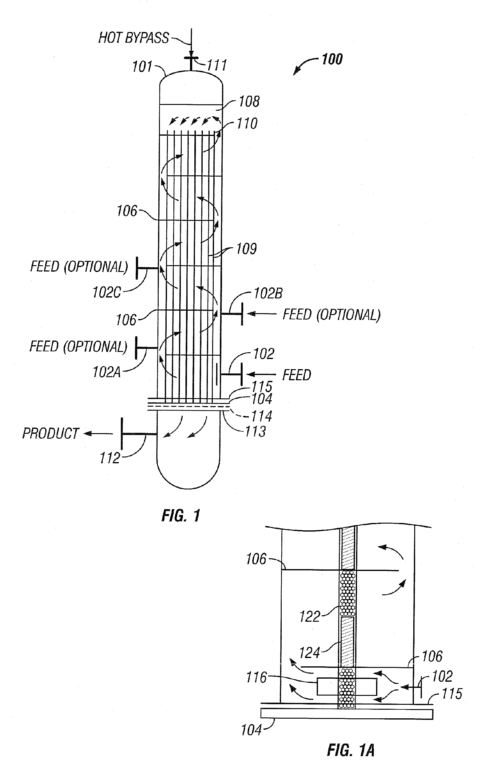
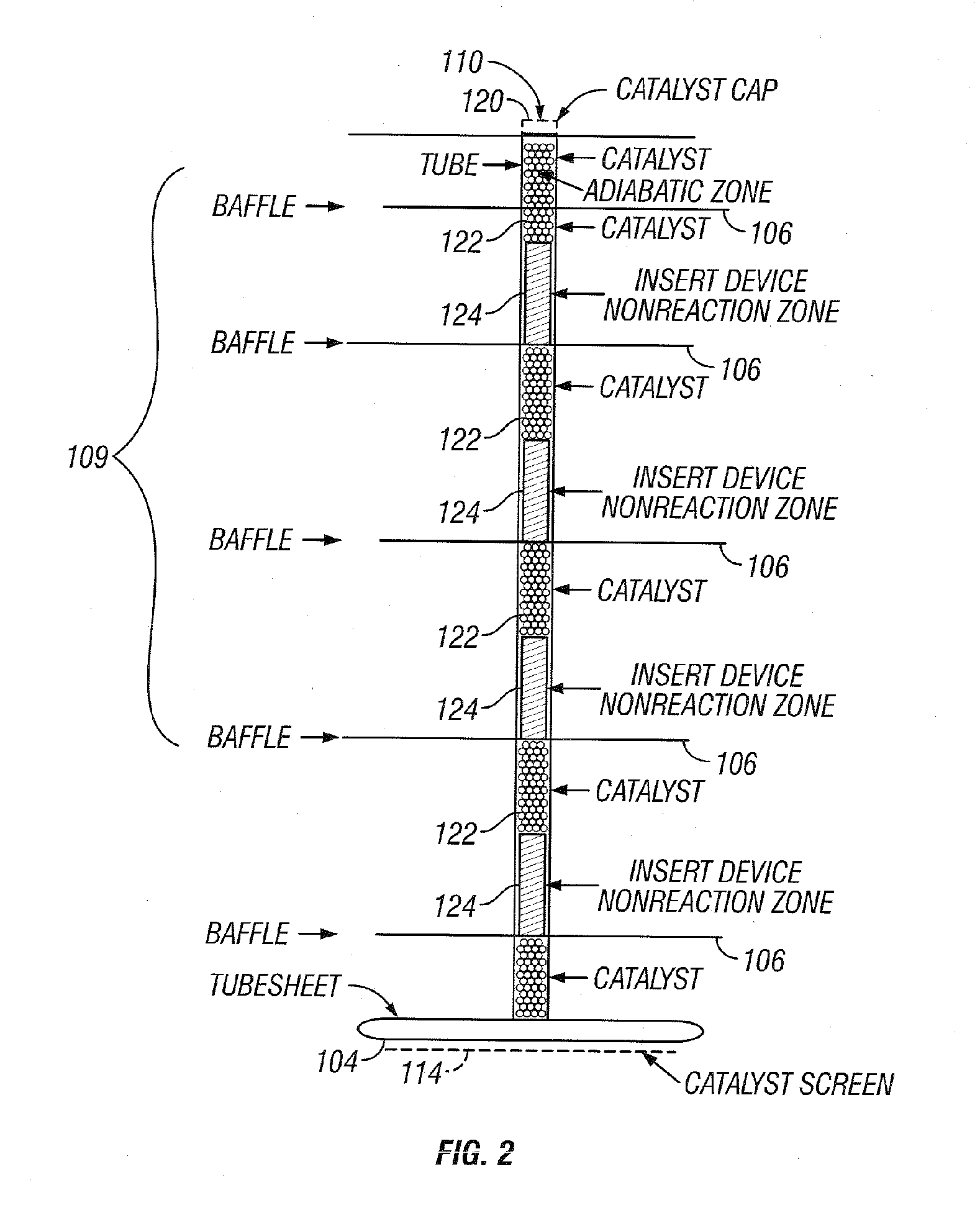
[0036] The invention will be described by way of examples with reference to FIGS. 1-13 which are not to be construed as a limitation upon the apparatus elements and process steps of the invention. The present invention is directed to a synthesis reactor for exothermic reactions which can better approximate the equilibrium temperature / concentration curve for the conversion of reactants to products. Catalyst usage and reaction yields can be improved over existing isothermal and staged adiabatic reactor processes. The advantages of the present invention are accomplished by withdrawing heat from the catalyst-filled tubes of the converter to maintain the reaction temperature within the bulk of the length of the catalyst-filled tubes close to an optimum. Within this application the terms reactor and converter can be used interchangeably.

[0037] Examples of commercially practiced exothermic-type gas phase catalytic reactions which can be practiced in reactor 100, as depicted in FIG. 1, inc...


PUM

PropertyMeasurementUnit
equilibrium temperatureaaaaaaaaaa
diameteraaaaaaaaaa
diameteraaaaaaaaaa

Abstract

An ammonia converter system and method are disclosed. The reactor can alter the conversion of ammonia by controlling the reaction temperature of the exothermic reaction along the length of the reactor to parallel the equilibrium curve for the desired product. The reactor 100 can comprise a shell 101 and internal catalyst tubes 109. The feed gas stream enters the reactor, flows through the shell 101, and is heated by indirect heat exchange with the catalyst tubes 109. The catalyst tubes 109 comprise reactive zones 122 having catalyst and reaction limited zones 124 that can comprise inert devices that function to both separate the reactive zones, increase heat transfer area, and reduce the temperature of the reaction mixture as the effluent passes through the catalyst tube 109.

Description

BACKGROUND OF THE INVENTION [0001] This invention relates to a converter for exothermic reactions, and more particularly to a converter and method such as for converting nitrogen and hydrogen to ammonia whereby reduced catalyst usage and / or greater product yields are obtainable. [0002] Ammonia is commonly manufactured by reacting nitrogen and hydrogen in a synthesis loop which can include a compressor, an ammonia synthesis reactor, and an ammonia condensation and recovery step. Unreacted synthesis gas from the synthesis reaction is typically recycled from the ammonia separator back to the compressor and reactor. The synthesis gas can contain argon, methane, and other inert components which are typically removed as a purge stream, thereby avoiding buildup of inerts in the synthesis loop. The purge gas can be further processed in a hydrogen recovery unit, or alternatively supplied directly to the fuel system with or without additional treatment or hydrogen recovery. [0003] Many ammoni...

Claims


Application Information

Patent Timeline
Patent Type & Authority Applications(United States)
IPC IPC(8): C01C1/04
CPCB01J8/008B01J8/067B01J23/462B01J2208/00212B01J2208/00221C01C1/0441B01J2208/00548B01J2219/00238C01C1/0423C01C1/0482Y02E60/364B01J2208/00513Y02P20/52Y02E60/36
Inventor SINGH, SHASHI P.MANN, DAVID P.PISUT, ANANT
Owner KELLOGG BROWN & ROOT LLC
Why Eureka
Try Eureka