Fluidized bed device

a bed and flue technology, applied in the direction of lighting and heating apparatus, furnaces, separation processes, etc., can solve the problems of low product yield, disadvantageous increase in air consumption, and difficulty in practicability, and achieve low product production cost, high disintegration effect, and low production cost

Inactive Publication Date: 2006-05-18
POWREX
View PDF4 Cites 5 Cited by
  • Summary
  • Abstract
  • Description
  • Claims
  • Application Information

AI Technical Summary

Benefits of technology

[0016] (4) The disintegrator mechanism equipped with the impeller and the screen does not exert such a disintegration force as to disintegrate single particles but is capable of disintegrating solely the secondary agglomerates of particles or aggregates of excessively agglomerated particles. Accordingly, there is relatively little generation of fines due to abrasion wear of the particles, thus ensuring a high product yield. Further, the target finish particle size can be readily controlled through appropriate selection of the configuration and RPM of the screen or impeller. Further, the friction effect is imparted to the particles in the gap space between the impeller and the screen, whereby, in the case of wax coating on the particles, for example, the so-called dry coating process can be performed by gradually adding small amounts of wax powder as it is in the form of powder while allowing nuclear particles to fluidize and circulate within the processing container.
[0017] (5) The disintegrator mechanism equipped with the rotor and the stator each having a plurality of concentrically arranged teeth provides a high disintegration effect on the secondary agglomerates of particles or aggregates of excessively agglomerated particles, and further exerts strong suction / extrusion action on powder particles, whereby there is relatively little build-up of particles in the peripheral portions of the disintegrator mechanism, thereby further facilitating good fluidization and circulation of powder particles in the processing container.

Problems solved by technology

However, this involves many problems in terms of product manufacture costs, such as the prolonged processing time due to the low spray rate of the spray solution or the necessity of performing numerous experiments to grasp the characteristics of the spray solution prior to setting the spray rate of the spray solution.
However, to attain the anticipated effect, it is necessary to spray considerably high-pressure compressed air from a number of spray nozzles, which disadvantageously increases the consumption of air not contributing to the drying of particles.
Further, it has been practically difficult, even by optimizing the spray rate of the spray solution or by dispersing particles with compressed air, to effect coating processing on particles having a fine particle size, for example, fine particles with a particle size of 100 μm or less, particularly those with a particle size of 50 μm or less, without involving secondary agglomeration, or to produce product particles with a sharp particle size distribution in granulation processing for obtaining the above-mentioned particle sizes as the final particle sizes.

Method used


Image

  • Fluidized bed device
  • Fluidized bed device
  • Fluidized bed device

Examples


Embodiment Construction

[0026] Hereinbelow, an embodiment of the present invention is described with reference to the drawings.

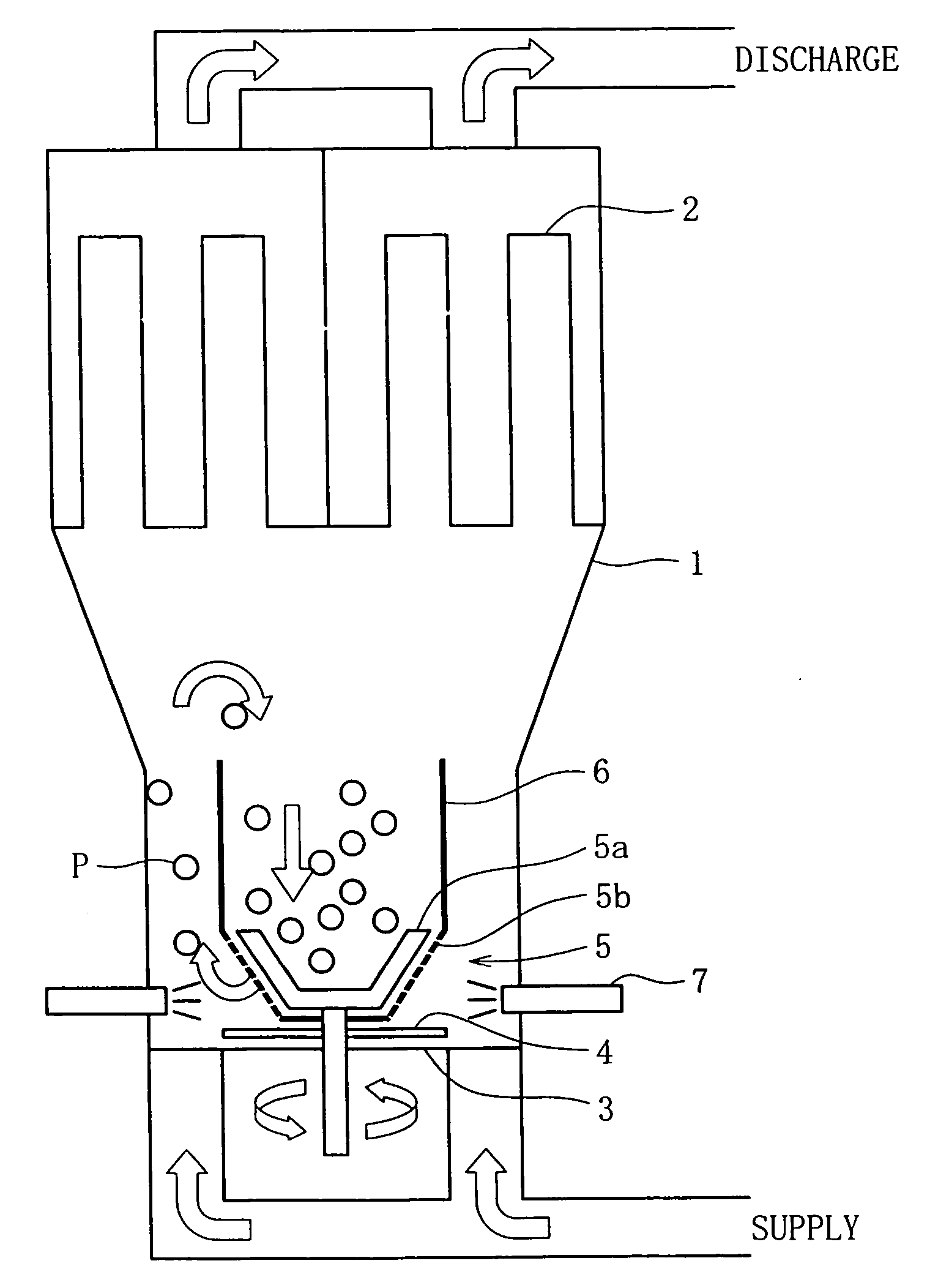
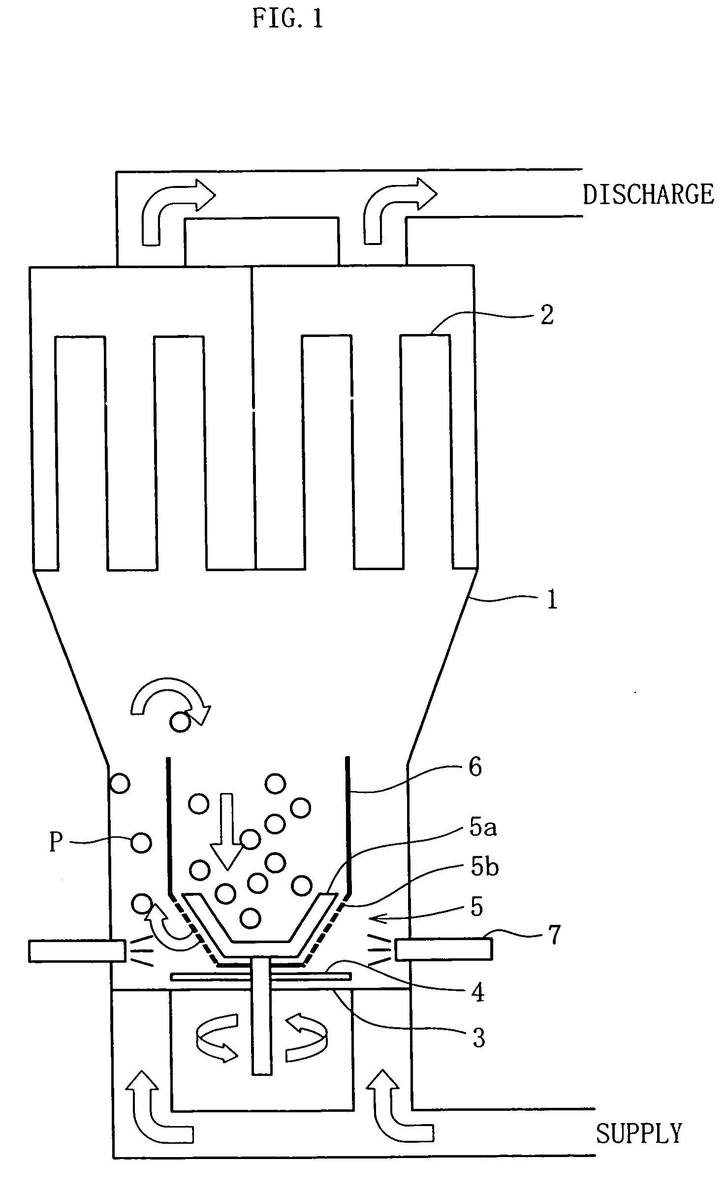
[0027]FIG. 1 conceptually illustrates the overall construction of a fluidized bed apparatus according to this embodiment.

[0028] A processing container 1 has a conical upper part and a cylindrical lower part, for example (or a cylindrical upper part and a conical lower part), with a filter system 2 installed in the space above the processing container 1 and a gas dispersion plate 3 consisting of a porous plate such as punching metal arranged at its bottom. Further, a rotary rotor 4 is arranged at the bottom center of the processing container 1, a disintegrator mechanism 5 is arranged above the rotary rotor 4, and a cylindrical draft tube 6 is installed above the disintegrator mechanism 5. Further, one or a plurality of spray nozzles 7 are arranged by the side of the disintegrator mechanism 5.

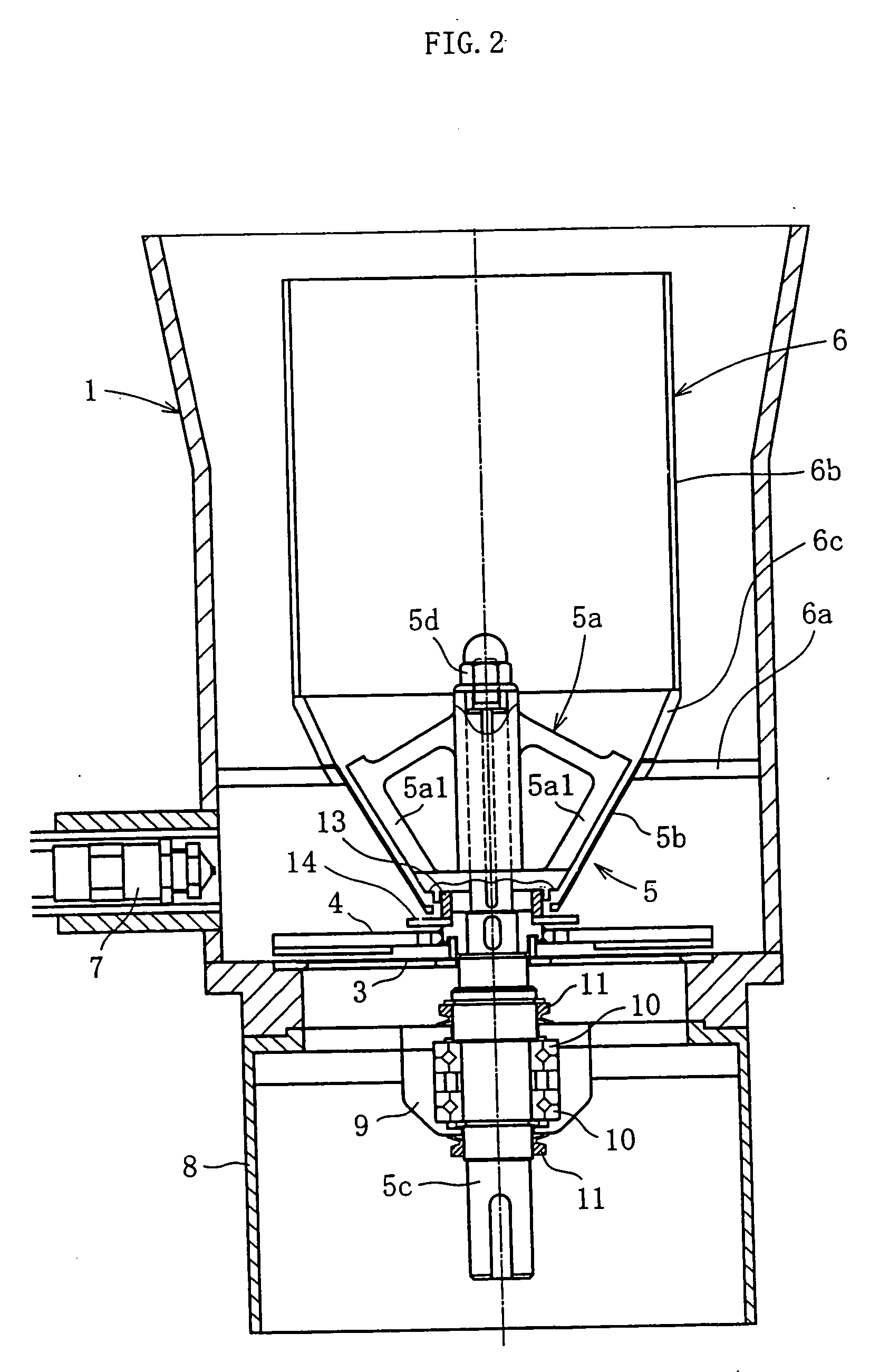
[0029]FIG. 2 shows the lower part of the processing container 1.

[0030] The draft tube 6 ...


PUM

PropertyMeasurementUnit
particle sizesaaaaaaaaaa
particle sizeaaaaaaaaaa

Abstract

A fluidized bed apparatus has a rotary rotor 4 arranged at the bottom center thereof, a disintegrator mechanism 5 arranged above the rotary rotor 4, and a cylindrical draft tube 6 installed above the disintegrator mechanism 5. A fluidizing gas jetted from a gas dispersion plate 3 causes powder particles P in a processing container 1 to form a fluidized bed in which they circulate so as to ascend through the gap between the outer periphery of the rotary rotor 4 and the bottom inner wall of the processing container 1, the space between the disintegrator mechanism 5 and the inner wall of the processing container 1, and the space between the outer periphery of the draft tube 6 and the inner wall of the processing container 1, and descend through the inner portion of the draft tube 6.

Description

BACKGROUND OF THE INVENTION [0001] The present invention relates to a fluidized bed apparatus used in the production of fine particles, granules, etc. of pharmaceutical preparations, agricultural chemicals, food products, etc., and more specifically to a fluidized bed apparatus suitable for coating processing on particles of a fine particle size or granulation processing of particles with a fine final particle size. [0002] A fluidized bed apparatus generally performs granulation or coating by spraying a spray solution (coating solution, binder solution, etc.) from a spray nozzle while forming a fluidized bed of powder particles within a processing container by using fluidizing gas introduced from the bottom of the processing container. Of the fluidized bed apparatuses of this type, those involving rolling, jetting, stirring, etc. of the powder particles are referred to as a compound fluidized bed apparatus. [0003]FIG. 8 shows a fluidized bed apparatus (commonly called “Wurster type ...

Claims


Application Information

Patent Timeline
Patent Type & Authority Applications(United States)
IPC IPC(8): F27B15/00B01J8/18B01J2/00B01J2/16B01J8/00B01J8/38
CPCB01J2/006B01J2/16B01J8/006B01J8/1818B01J8/1854B01J8/1863B01J8/38B01J8/382B01J8/386
Inventor NATSUYAMA, SUSUMUWATANABE, NOBUYUKIOTAKI, KAZUYOSHINAGATSUMA, KENJINAGATO, TAKUYAKANOH, YOSHIYUKITABATA, RANKOBAYASHI, MAKOTO
Owner POWREX
Why Eureka
Try Eureka