Briquetting process

a briquetting process and briquetting technology, applied in the field of briquetting materials processing and system, can solve the problems of reducing the calorific value of coal, preventing greater acceptability and use of such coals, sub-bituminous coals suffering serious spontaneous combustion problems, and considerable size degradation, so as to reduce voids and minimise or avoid blowback of gases

Active Publication Date: 2006-06-01
K R KOMAREK +3
View PDF18 Cites 20 Cited by
  • Summary
  • Abstract
  • Description
  • Claims
  • Application Information

AI Technical Summary

Benefits of technology

[0033] Preferably, the partially dried particulate matter is fed to the briquetting apparatus under conditions such that water vapour is released from the particulate matter whereby the released water vapour substantially displaces and / or prevents the ingress of a large proportion of other gaseous components from the atmosphere surrounding and / or intermixed with the particulate matter. More preferably, the particulate matter that is fed to the briquetting apparatus is surrounded by and / or intermixed with a gaseous component containing from 70-100% by volume water vapour at the point where it enters the briquette-forming part of the briquetting apparatus. As a result, when the particulate matter is compressed during briquette formation, the water vapour condenses or liquefies and the pressure buildup of gaseous material in the thus-formed briquette is minimised. The present inventors have also discovered that previous difficulties caused by the presence of large proportions of non-condensable gases mixed with the particulate matter (which include blow-back of the gases through the particulate feed material which can disrupt the flow of particulate matter to the briquetting apparatus, explosive break-up of the briquettes as they are removed from the briquetting apparatus and porous briquettes of diminished strength) are minimised or avoided in the present invention.
[0037] forming briquettes in a briquette forming part of the briquetting apparatus, wherein briquettes are formed from the particulate matter under conditions of temperature and pressure which cause the condensable gas to condense, thereby reducing gas pressure buildup of gaseous components during briquette formation.
[0041] means for introducing a condensable gas into the briquetting apparatus, wherein the briquette forming apparatus includes a briquette forming part in which briquettes are formed from the particulate matter under conditions of temperature and pressure which cause the condensable gas to condense during briquette formation, thereby reducing the gas pressure buildup.
[0048] It is a feature of the first aspect of the present invention that further drying of the partially dried particulate matter takes place during feeding of the particulate matter to the briquetting apparatus. As will be readily understood by the person of skill in the art, further drying of the particulate matter during feeding to the briquetting apparatus causes the release of moisture from the particulate matter. The moisture is released in the form of water vapour and the water vapour acts to displace non-condensable gases, such as nitrogen, carbon dioxide and other gases from the atmosphere that surrounds or intermixes with the particulate matter. As a result, the gaseous component of the mixture of particulate matter and gas that is fed to the briquetting apparatus has a high level of water vapour. It will be appreciated that water vapour is a condensable gas and that the pressure applied to the particulate matter during the briquetting process can cause the water vapour to liquefy, thereby greatly reducing the volume of the gaseous components that pass through the briquetting apparatus. This assists in preventing blow-back of gases through the particulate matter being fed to the briquetting apparatus, as well as improving the quality of the briquettes thus formed by minimising porosity caused by trapped non-condensable gases and possible explosive breakdown of briquettes caused by pockets of compressed non-condensable gases trapped inside the briquettes.
[0055] In order to assist in feeding the particulate matter to the briquetting apparatus or briquetting rollers, it is preferred that one or more feed augers are used to feed the particulate matter. The feed augers are beneficial as they precompact the particulate matter, reduce voidage, and ensure a consistent supply of particulate matter to the briquetting apparatus. Moreover, the feed augers generate a more tortuous path for escaping gas displaced from between the particles during compaction which also assists in minimising or avoiding blow-back of gases through the particulate matter being fed to the briquetting apparatus.

Problems solved by technology

Not only does this reduce the calorific value of the coal, it almost completely excludes sub-bituminous coals from export markets due to the poor economics associated with transporting the very high moisture levels associated with those coals.
However, removal of the water causes further problems that prevent greater acceptability and use of such coals.
In particular, once dried, the sub-bituminous coals suffer serious spontaneous combustion problems and considerable size degradation.
Consequently, the drying process tends to increase the quantity of fines associated with the coals.
Although more amenable to transport than sub-bituminous coals, bituminous coals can suffer from production of excessive fines during mining, washing and handling operations.
Such fines are difficult to use and represent a loss of product.
Free surface moisture also causes difficulties with fine bituminous coals and can be as high as 25% by weight.
This causes problems because it reduces the available energy content of the coal and can have a serious impact on the handling properties of the coal.
With many metallurgical and higher ranks steam coal, the grindability of the coal is such that the percentage of fine material in the total cleaned coal is sufficient to result in marketing difficulties even if the moisture content is reduced to an otherwise acceptable value.
However, the briquetting solution must provide for restructuring of the fines into a commercially attractive, handleable and durable form whilst not increasing production costs beyond the threshold of overall profitability.
Experience with coal briquettes that incorporate binders has shown that a generally applicable coal binder that meets all of the above criteria has not yet been found.
For example, pitch, bitumen and asphalt give adequate strength and moisture resistance but result in smoking combustion, toxicity problems, change to coking properties, high cost and high processing costs.
Starch provides good strength and clean burning but is expensive and has poor weathering resistance.
Sulphate liquor binders burn with little smoke but produce toxic sulphur dioxide emissions and have poor weathering properties.
Sugars, particular molasses, have inferior moisture and weathering resistance and may suffer mould growth during storage.
Cellulose-type binders typically suffer from low strength and rapid deterioration, with the briquettes tending to disintegrate in the early stages of combustion.
It has been reported that the inorganic binders all suffer relatively low strengths, poor weathering resistance and high ash levels after combustion.
The necessity to add the binder component to the briquette also unavoidably increases the complexity and cost of briquette production.
In particular, the coal particles are fed to a hot gas stream in a flash dryer and the thermal shock of the particles entering the hot gas stream causes degradation of the coal particles.
It has been also noted, however, that briquette quality began to decline if the material was heated to a temperature in excess of 220° F.

Method used


Image

  • Briquetting process
  • Briquetting process
  • Briquetting process

Examples


Embodiment Construction

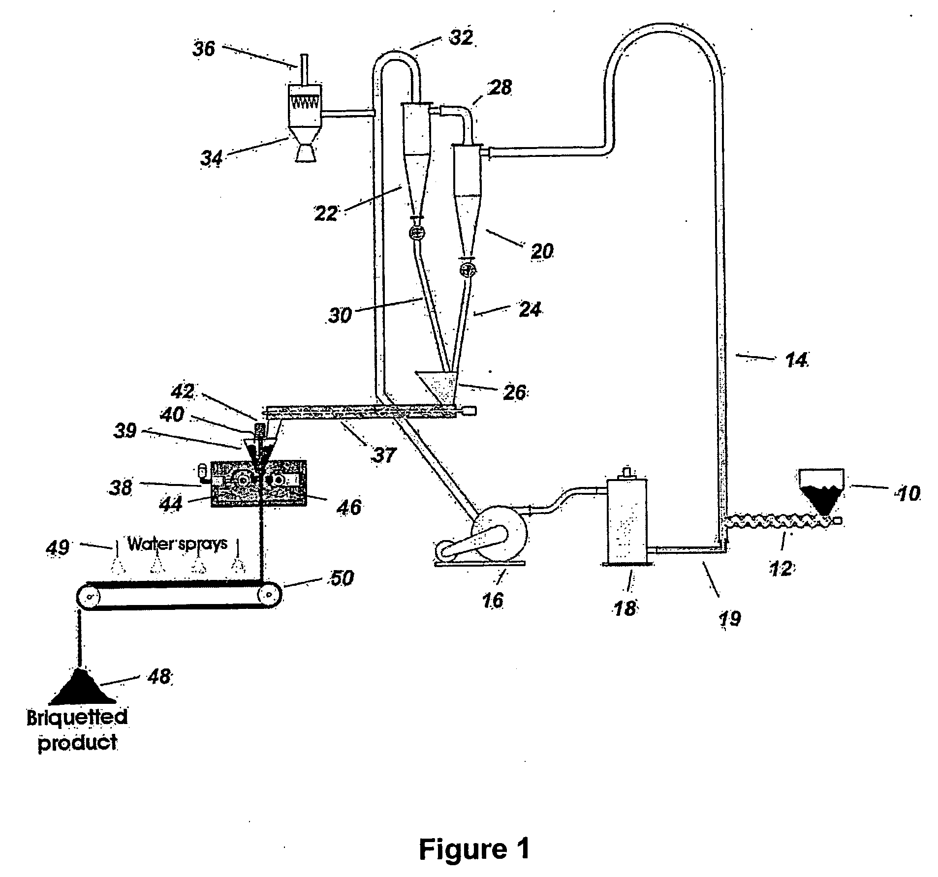
[0064] In order to more fully explain the present invention, an embodiment of the invention will now be described with reference to FIG. 1, which shows schematic flow diagram of a process for forming briquettes from bituminous coals or sub-bituminous coals. Although the process shown in FIG. 1 is intended for use in bituminous or sub-bituminous coals, it will be appreciated that the process of the first and second aspects of the present invention may be used to form briquettes from other particulate material.

[0065] In the flow diagram shown in FIG. 1, moist coal is fed from a moist coal hopper 10 through an auger conveyer 12 into a flash heater riser tube 14. A hot gas stream passes through flash heater riser tube 14. The hot gas stream is generated by passing gas from a fan 16 through a gas heater 18 into the flash heater riser tube 14.

[0066] When the moist coal feed is fed into the flash heater riser tube 14, the coal is entrained in the gas stream. As the gas is hot, the temper...


PUM

PropertyMeasurementUnit
temperatureaaaaaaaaaa
diametersaaaaaaaaaa
diameteraaaaaaaaaa

Abstract

A process and system is provided for briquetting particulate matter such as moisture-containing bituminous and sub-bituminous coal. This process includes partially drying the particulate matter and feeding, the partially dried particulate matter to a briquetting apparatus under conditions such that water vapour is released from the particulate matter during feeding. The particulate matter is passed through briquette forming rollers to form briquettes. The released water vapour substantially displaces or prevents the ingress of a large proportion of other gaseous components from the atmosphere surrounding an / or intermixed with the particulate matter. The particulate matter that is fed to the briquetting apparatus is surrounded by and intermixed with a gaseous component containing 70 to 100% by volume of water vapour at the point where it enters the briquette-forming part of the briquetting apparatus, such that when the particulate matter is compressed during briquette formation, the water vapour liquefies and the pressure buildup of gaseous material in the thus-formed briquettes is minimised. This reduction in the pressure buildup of gaseous components also acts to reduce blow-back of gases as the coal fines are being formed into briquettes.

Description

FIELD OF THE INVENTION [0001] The present invention relates to a process and system for briquetting materials, especially but not limited to those that contain moisture. The present invention is especially suitable for briquetting organic materials that contain moisture, such as peat, lignite, brown coal, sub-bituminous coal, bituminous coal and anthracite. BACKGROUND OF THE INVENTION [0002] The present invention is particularly suited to briquetting organic material containing moisture, such as peat, lignite, brown coal, sub-bituminous coal and bituminous coal. The present invention is especially suited to briquetting sub-bituminous and bituminous coals and, for convenience and ease of description, the invention will be described with reference to the briquetting of sub-bituminous and bituminous coals. However, it will be understood that the invention is not limited to briquetting bituminous and sub-bituminous coals and that the invention may be used to briquette other organic or i...

Claims


Application Information

Patent Timeline
Patent Type & Authority Applications(United States)
IPC IPC(8): C10L5/40C10L5/06C10L5/08C10L5/24
CPCC10L5/08C10L5/24C10L5/361C10L5/44Y02E50/10Y02E50/30B30B11/16B30B15/308C10L2290/30
Inventor CLARK, KEITH NORMANKALB, GEORGE WILLIAMKOMAREK, RICHARDMEAKINS, ROSS LAWRENCEPEARSON, ARTHUR CLIVE
Owner K R KOMAREK
Why Eureka
Try Eureka