
Apparatus for Dispensing a Sample in Electrospray Mass Spectrometers

Inactive Publication Date: 2006-06-01
DIAGNOSWISS
View PDF21 Cites 59 Cited by
  • Summary
  • Abstract
  • Description
  • Claims
  • Application Information

AI Technical Summary

Benefits of technology

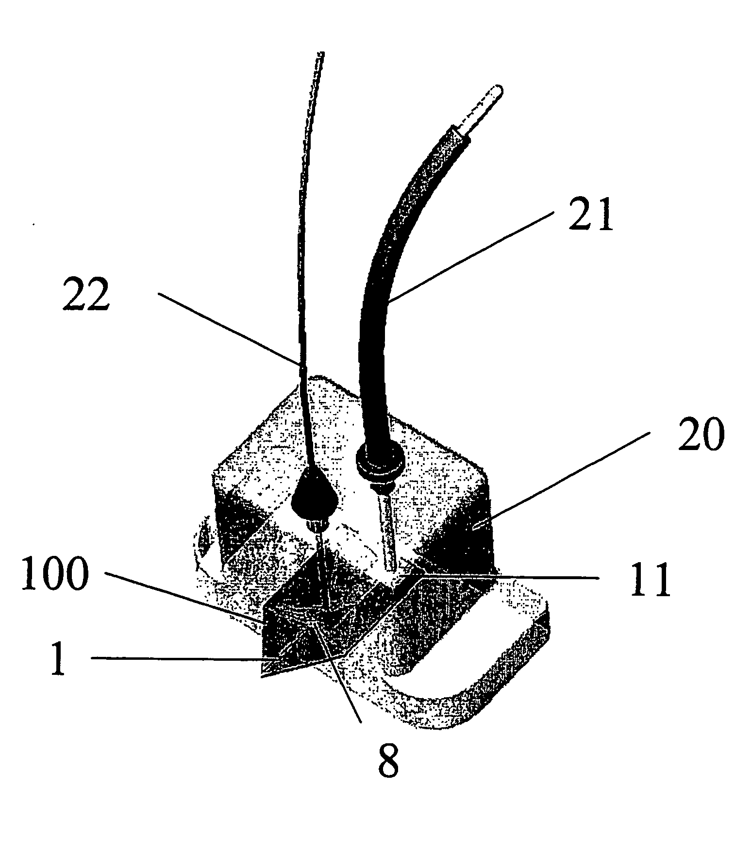
[0014] In one embodiment of the invention, the microstructures are formed in the same plane, so that the outlets of the sample microstructure and of the sheath liquid microstructure are adjacent. In another embodiment, the microstructure outlets are not in the same plane or even one over the other. In this case, the substrate may be a multilayer body, one layer comprising one of said at least two microstructures and another layer comprising a second of said at least two microstructures. In another option, one microstructure may be formed on one side of the polymer substrate, whereas the second microstructure is formed on the opposite side of the polymer substrate. In a further option, one microstructure may be formed in the cover used to seal the other microstructure (this can notably be the case of a micro-hole formed in the lamination layer used to seal the sample microstructure, said micro-hole being directly used to introduce the sheath liquid solution at or close to the outlet of the sample microstructure where the spray is then generated). For ease of manipulation, it may be advantageous if all microstructures have access holes (or inlet reservoirs) on the same side of the polymer substrate.
[0031] From a second aspect, the present invention provides a method of dispensing a sample into a mass spectrometer from an apparatus as defined above. The method is characterized in that the electric field may be applied in both the sample and the sheath liquid microstructures and that the flow-rates of the solutions contained in these two microstructures may thus be controlled, thereby allowing to control the mixing of sample and sheath liquid solutions in the Taylor cone and hence their proportion in the spray. The method of this invention may advantageously be used for dispensing an aqueous sample solution into a mass spectrometer, even at high as well as at low flow rates, and even at high pH values.

Problems solved by technology

This requirement is sometimes incompatible with pre-spray activities that need to be performed for analytical, separation and / or purification purposes or that are required due to the specific properties of these volatile elements of the spray.
Again, these systems are efficient when the flow rates are large enough and well-controlled, but they often create quite large dead volumes which induce sample dilution and hence affect the sensitivity as well as the resolution of the detection.
In a nanoelectrospray, i.e. when the flow-rate is smaller than 5 microL / min, a liquid junction can also be used, but it is very difficult to control it efficiently because the pressure applied to the sheath liquid to mix with the solution to be sprayed often destabilizes the flow in the main sample capillary.
In case of separation, this may deeply reduce the resolution of the separated peaks.
Finally, when the system is used for electrophoresis, the pressure applied on the sheath liquid can counter the electroosmotic flow and render the plug profile distorted which decreases the resolution of the separation.
In microanalytical devices, the possibility of fabricating different channels and interconnecting them on the same chip enables one to create liquid junctions with a minimum of dead volume, which reduces the sensitivity and resolution losses.
Nevertheless, the main difficulty in electrospray and nanospray sampling with sheath liquids is to control the flow-rate of the sheath liquid and that of the sample solution.
The microfluidic control in these systems is yet quite difficult and necessitates to fill the different arms of the chip without bubbles before starting the spray with real samples.
One of the main drawbacks is that the trypsine, which can work in organic solutions, needs a pH of 8.2 to operate, whereas the spray would be more efficient at a pH of 3.
As the volume and the flow rate are too small in the nanoelectrospray, it is difficult to introduce a liquid junction to add the sheath liquid.
Therefore, these kinds of direct monitoring of reactions are very limited and are not yet considered as analytical tools.

Method used


Image

  • Apparatus for Dispensing a Sample in Electrospray Mass Spectrometers
  • Apparatus for Dispensing a Sample in Electrospray Mass Spectrometers
  • Apparatus for Dispensing a Sample in Electrospray Mass Spectrometers

Examples


Embodiment Construction

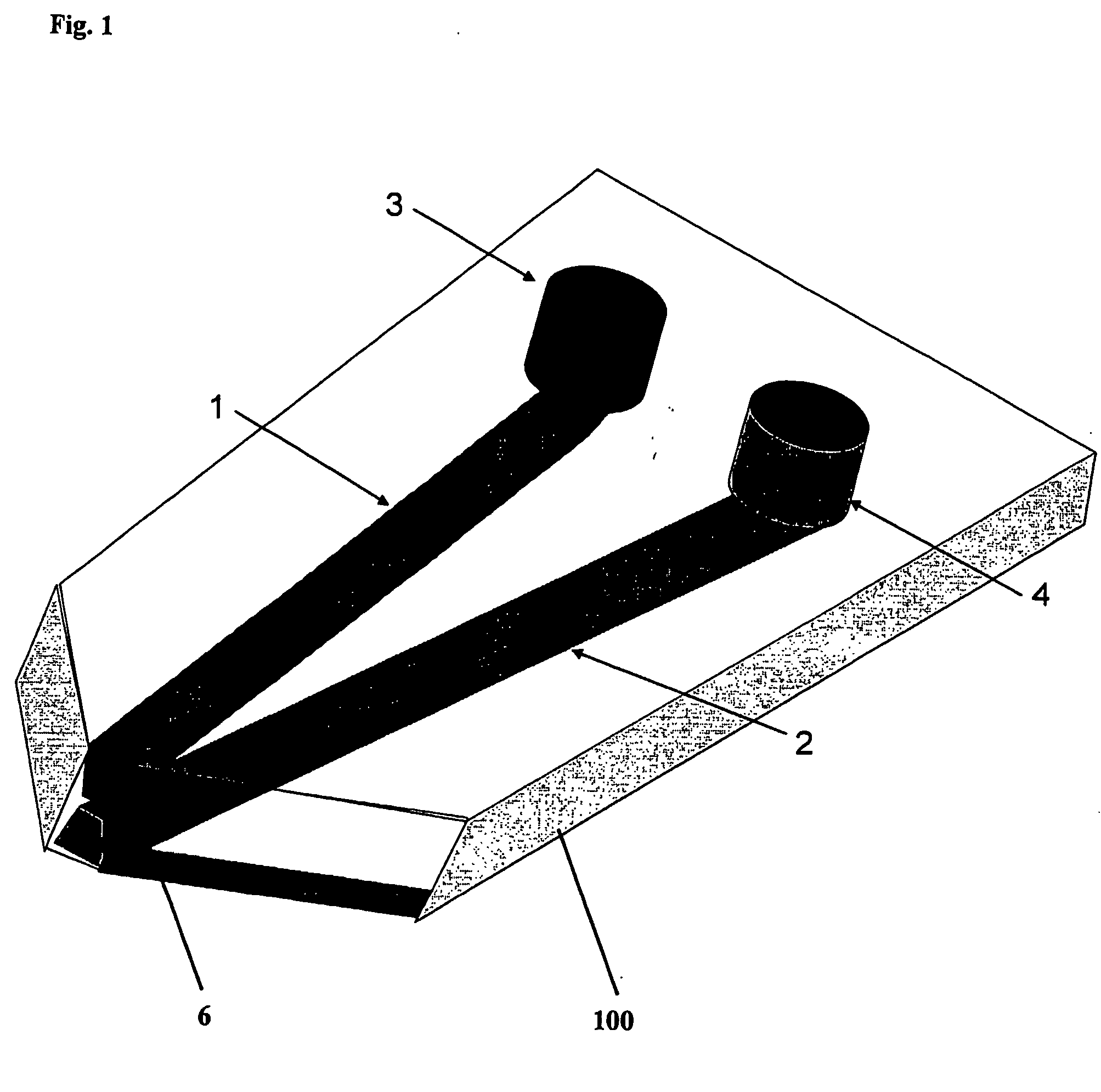
[0054]FIG. 1 is an example of apparatus according to the present invention which is made in a substrate 100 and which comprises two covered microstructures, namely a sample microchannel 1 and a sheath liquid microchannel 2 that are connected to inlet reservoirs 3, 4 respectively, placed on the same side of the support 100 for fluid introduction. FIG. 1 also illustrates that the microstructures have an outlet 6 formed at the edge of the support, at which the spray is to be generated upon voltage application.

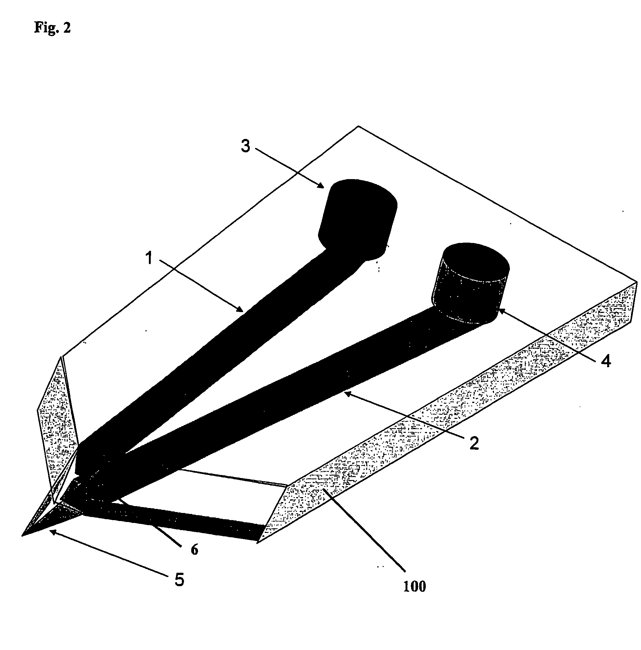
[0055]FIG. 2 shows the apparatus as in FIG. 1, with the Taylor cone 5, formed upon potential application, encompassing the outlets 6 of both the sample and sheath liquid microchannels, so that the sample solution mixes with the sheath liquid solution directly in the Taylor cone.

[0056]FIG. 3A shows an example of an array of apparatuses fabricated on the same support 100, said apparatuses comprising one sample microstructure 1, one sheath liquid microstructure 2 and one supplement...


PUM

PropertyMeasurementUnit
Thicknessaaaaaaaaaa
Lengthaaaaaaaaaa
Pressureaaaaaaaaaa

Abstract

The present invention relates to an apparatus to dispense a sample for subsequent electrospray ionisation (ESI) mass spectrometry (MS) analysis, to a method of fabricating such apparatus and to applications of such apparatus in biological and chemical analysis. The apparatus consists of an electrically non-conductive substrate comprising at least two covered microstructures (generally microchannels) having one extremity formed at the edge of the substrate, one of said microstructures containing the sample to be dispensed into a mass spectrometer by electrospray ionisation and at least a second of said microstructure containing a fluid used as sheath liquid or sheath gas, said at least two microstrctures being formed in such a manner that the sample and the sheath liquid / gas come in contact to each other and / or are mixed directly in the Taylor cone of the spray.

Description

BACKGROUND OF THE INVENTION [0001] In mass spectrometry (MS), one of the intrinsic features of efficient electrospray or nanoelectrospray processes is the need to add volatile buffer and / or solvent to the sample in order to enable efficient evaporation in a controlled buffering environment. This requirement is sometimes incompatible with pre-spray activities that need to be performed for analytical, separation and / or purification purposes or that are required due to the specific properties of these volatile elements of the spray. Mixing Sheath Liquid and Sample after a Separation [0002] Different strategies have been presented to overcome this problem, which often consist in adding a pressurised flux conventionally called sheath liquid (often methanol, acetonitrile and acetic or formic acid) at the spraying orifice in order to mix the solution to be sprayed with this sheath liquid. In other systems, a sheath gas (i.e. a pressurised flux of gas, e.g. argon) is used to favour the eva...

Claims


Application Information

Patent Timeline
IPC IPC(8): H01J49/00H01J49/04
CPCH01J49/0018H01J49/167
Inventor ROSSIER, JOEL STEPHANEREYMOND, FREDERIC
Owner DIAGNOSWISS
Learn More