Antenna for portable terminal and portable terminal using same

a portable terminal and antenna technology, applied in the direction of antennas, antenna details, protective materials radiating elements, etc., can solve the problems of shortening the battery life of the portable terminal, and the like, so as to reduce the impedance change at the time of resonance, the antenna itself can be allowed to operate, and the band widen

Inactive Publication Date: 2006-06-08
OHMI TADAHIRO
View PDF24 Cites 33 Cited by
  • Summary
  • Abstract
  • Description
  • Claims
  • Application Information

AI Technical Summary

Benefits of technology

[0034] In this case, the mirror-image effect of an electric field can be utilized at the electric field symmetrical plane to thereby enable miniaturization of the antenna and, further, since the permittivity of the antenna itself can be reduced by the effect of the permeability, the impedance change at the time of resonance can be reduced to thereby enable broadening of the band.
[0035] Moreover, according to the antenna of this invention, the magneto-dielectric layer having a relationship of μrr>εrr where εrr represents the relative permeability and εrr the relative permittivity, is provided on the surface, opposite to the antenna mounting surface, of the reflecting plate. Therefore, the mirror-image effect is produced with respect to a magnetic field, thereby enabling an improvement in reflection characteristics and thus in antenna gain. Therefore, the radio wave can reach

Problems solved by technology

However, these Patent Documents 2, 3, and 4 each only propose the dielectric resonator antenna that can be improved in characteristics by using a dielectric having a high relative permittivity and improving the mounting and shape of the dielectric, but discuss nothing about improving a material of the dielectric forming the dielectric resonator antenna, or the like.
However, this publication refers to nothing about a dielectric resonator antenna that emits an electromagnetic wave to the exterior by radiating a radio wave into a resonator formed by a dielectric so that the radiated radio wave resonates in the dielectric.
When the nondirectional antenna is used in this manner, since the portable terminal radiates a radio wave, i.e. transmits the power, in all directions including the directions where no base station exists, this serves as a cause of shortening the battery life in the portable terminal.
However, in order to use such an antenna, there arises a problem that since the antenna is designed with respect to a wavelength in the air, it cannot be mounted to a portable terminal or the like without miniaturizing the antenna itself.
There has

Method used


Image

  • Antenna for portable terminal and portable terminal using same
  • Antenna for portable terminal and portable terminal using same
  • Antenna for portable terminal and portable terminal using same

Examples


embodiment 1

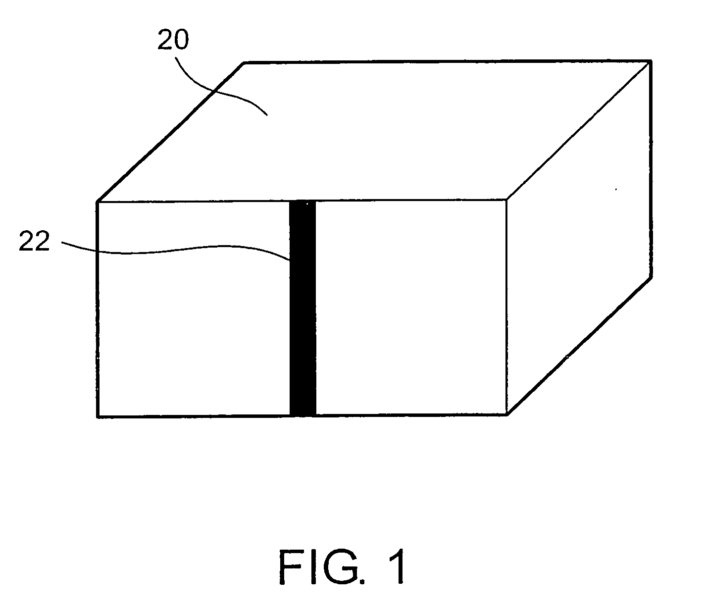
[0048] A resonator antenna according to an embodiment 1 of this invention will be described with reference to FIG. 1. FIG. 1 is a schematic diagram showing the resonator antenna according to the embodiment 1, wherein there are included a dielectric (insulator) 20 forming a resonator and a feeding electrode 22 for feeding the power to the resonator.

[0049] When manufacturing the illustrated magneto-dielectric 20, cobalt powder with a diameter of 50 nm and BST (barium strontium titanate) powder with a diameter of 0.5 μm were prepared and both powders were dispersed into an epoxy resin. In this case, 50 vol % cobalt and 10 vol % BST powder were dispersed with respect to the epoxy resin, then subjected to burning at 200° C. for one hour, and formed into a shape with a width of 14 mm, a length of 15 mm, and a thickness of 5.9 mm, thereby obtaining the illustrated dielectric 20. As a result of measuring the permittivity and permeability of this dielectric material by the cavity resonator ...

embodiment 2

[0058] Referring to FIG. 4, description will be given of a resonator antenna using a magneto-dielectric in an embodiment 2 of this invention.

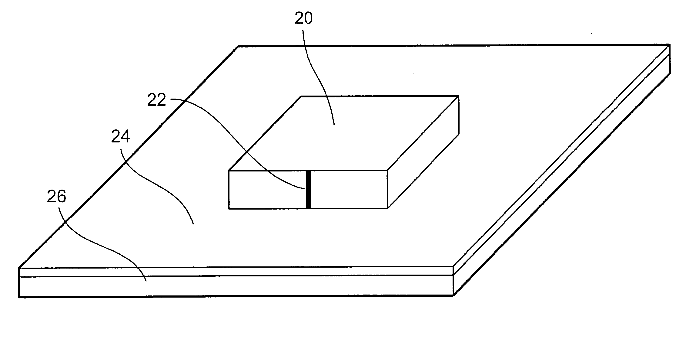
[0059] The resonator antenna according to the embodiment 2 shown in FIG. 4 comprises a resonator formed by a magneto-dielectric 20, which resonates a signal and emits it as a radio wave into the space, a feeding electrode 22 for feeding a signal to the resonator, a printed wiring board 24 for mounting thereon a body of the resonator, and a metal plate 26 which is located on a surface of the printed wiring board 24 on its side opposite to the antenna and terminates an electric field from the antenna so as to make a mirror image of the electric field. In this embodiment, a copper plate is used as the metal plate 26.

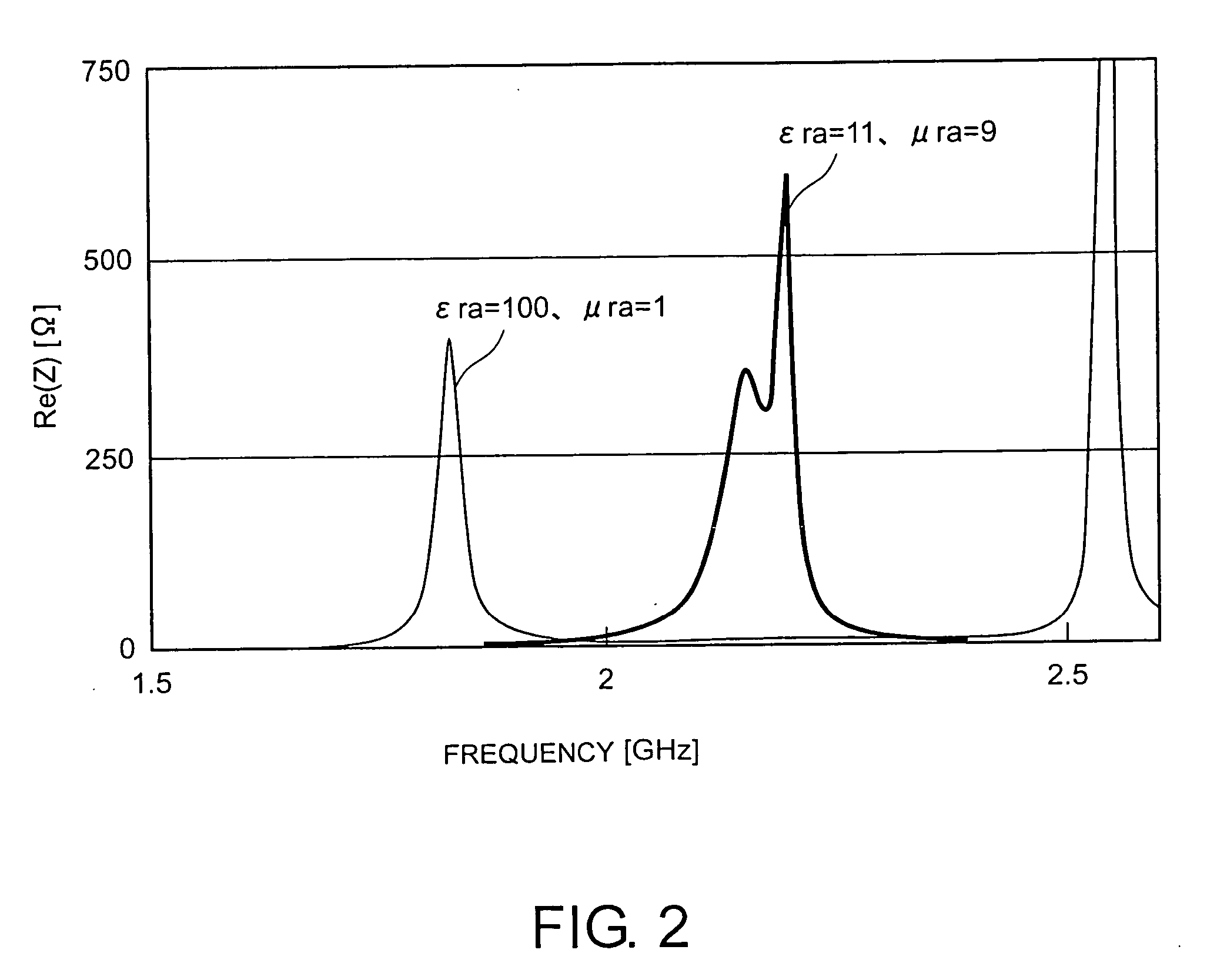
[0060] According to the same method as that in the embodiment 1, there was formed the resonator of the magneto-dielectric 20 having a width of 14 mm, a length of 15 mm, a thickness of 5.9 mm, εra=11, and μra=9 and then the feeding el...

embodiment 3

[0064] Referring to FIG. 6, description will be given of a resonator antenna using a magneto-dielectric in an embodiment 3 of this invention. The resonator antenna according to the embodiment 3 shown in FIG. 6 comprises a resonator formed by a magneto-dielectric 20, which resonates a signal and emits it as a radio wave into the space, a feeding electrode 22 for feeding a signal to the resonator, a printed wiring board 24 for mounting thereon a body of the resonator, and a magnetic layer 28 which is located at a surface of the printed wiring board 24 on its side opposite to the antenna and formed at the surface thereof opposite to its surface where the antenna is mounted.

[0065] Like in the embodiment 2, the resonator was formed by the magneto-dielectric 20 having a width of 14 mm, a length of 15 mm, a thickness of 5.9 mm, εra=11, and μra=9. The magneto-dielectric 20 was mounted, as an antenna element, on the printed wiring board 24 having a width of 5 cm, a length of 5.3 cm, and a t...


PUM


Abstract

A dielectric resonator antenna which emits an electric wave by having a dielectric body resonate is disclosed. A magnetic material is contained in the electric body, thereby increasing the relative permeability to more than 1 and lowering the relative permittivity. Consequently, the Q-value of the resonance can be lowered while maintaining the rate of wavelength shortening. With this technique, a broadband dielectric resonator antenna can be realized.

Description

TECHNICAL FIELD [0001] This invention relates to an antenna for a portable terminal and a portable terminal including such an antenna. BACKGROUND ART [0002] As portable terminals of this type, various devices such as portable telephones and PDAs have been proposed and widely spread. Normally, radio devices each comprising a transmitter and a receiver are mounted in the portable terminals for performing data communications with databases or the like or voice communications by radio. In order to perform the radio communications, these portable terminals are essentially provided with antennas, respectively. [0003] In this case, in order to enable reception even when the portable terminals are placed in any states, i.e. in order to ensure mobility of the portable terminals, the antennas of the portable terminals are normally nondirectional antennas. Therefore, as described above, these antennas are designed so as not to impede the advantages of the portable terminals, such as the mobili...

Claims


Application Information

Patent Timeline
IPC IPC(8): H01Q1/38H01Q1/40H01Q9/04
CPCH01Q9/0485
Inventor OHMI, TADAHIROMORIMOTO, AKIHIRONAKAMURA, FUMIAKI
Owner OHMI TADAHIRO
Why Eureka
Try Eureka