
Instruments and methods for adjusting separation distance of vertebral bodies with a minimally invasive spinal stabilization procedure

a technology of spinal stabilization and separation distance, which is applied in the field of instruments and methods for adjusting the separation distance of vertebral bodies with a minimally invasive spinal stabilization procedure, can solve the problems of destabilizing bone and affecting surrounding structures, pain and/or nerve damage, and altering the desired spacing between adjacent vertebrae, etc., to facilitate coupling the adjuster

Active Publication Date: 2006-06-08
ZIMMER BIOMET SPINE INC
View PDF27 Cites 265 Cited by
  • Summary
  • Abstract
  • Description
  • Claims
  • Application Information

AI Technical Summary

Benefits of technology

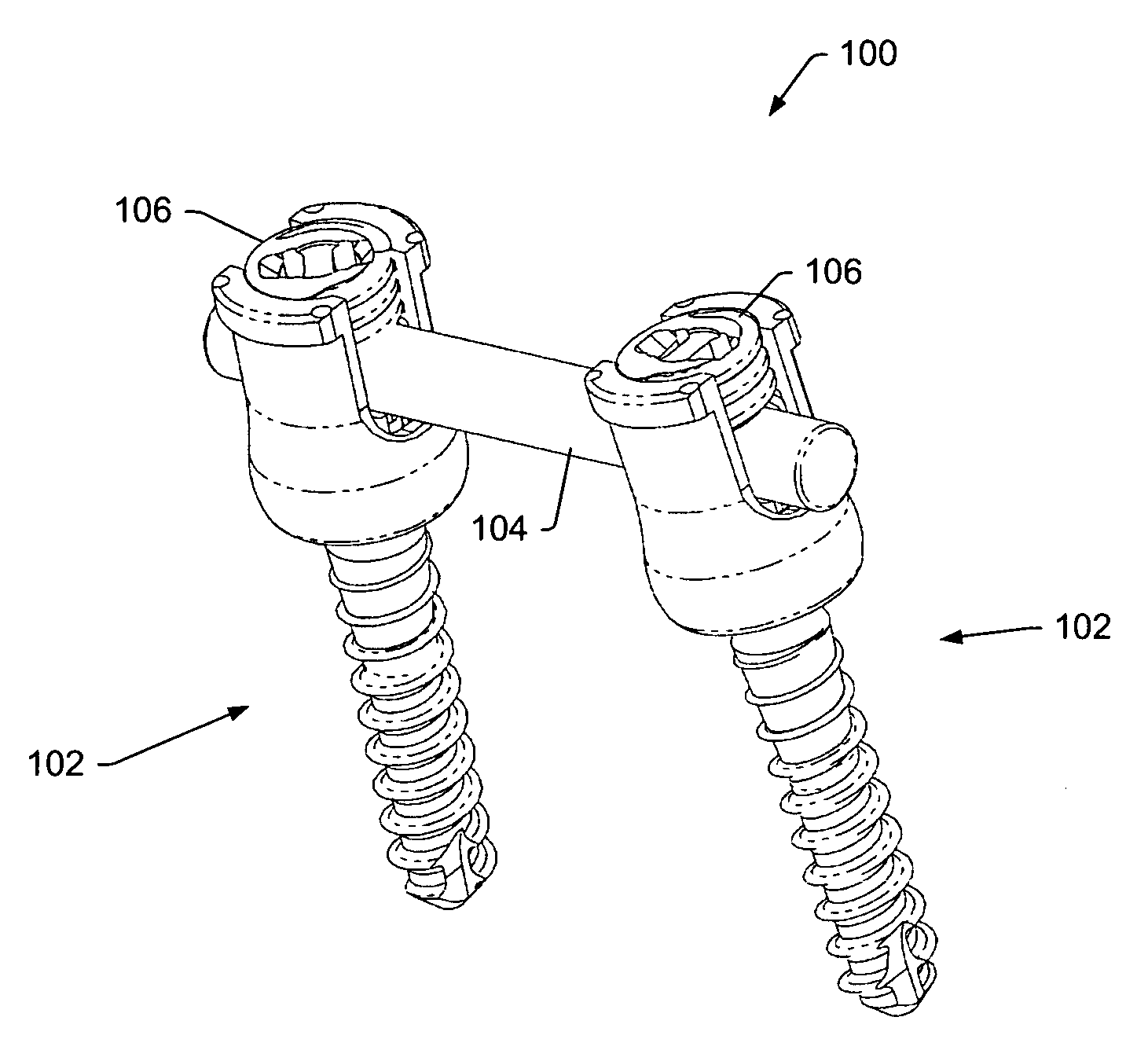
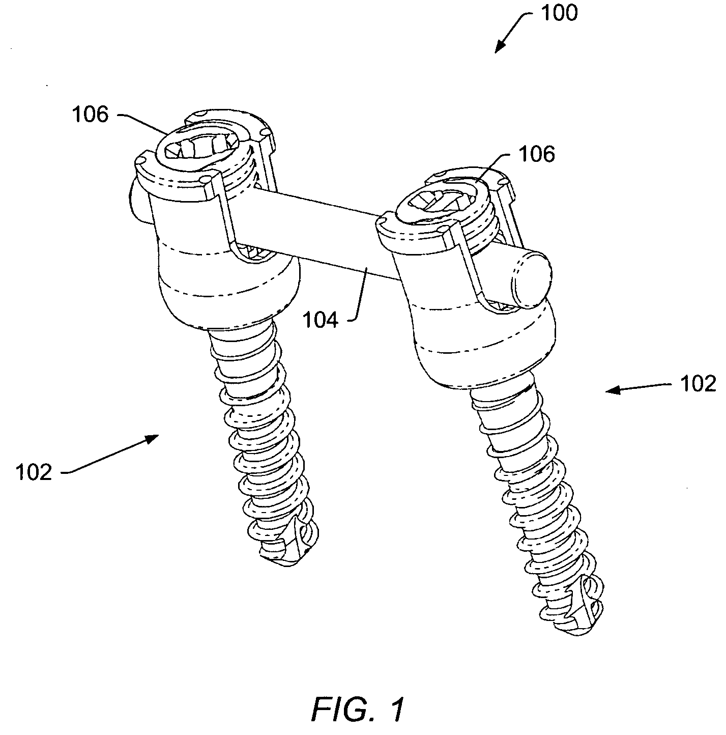
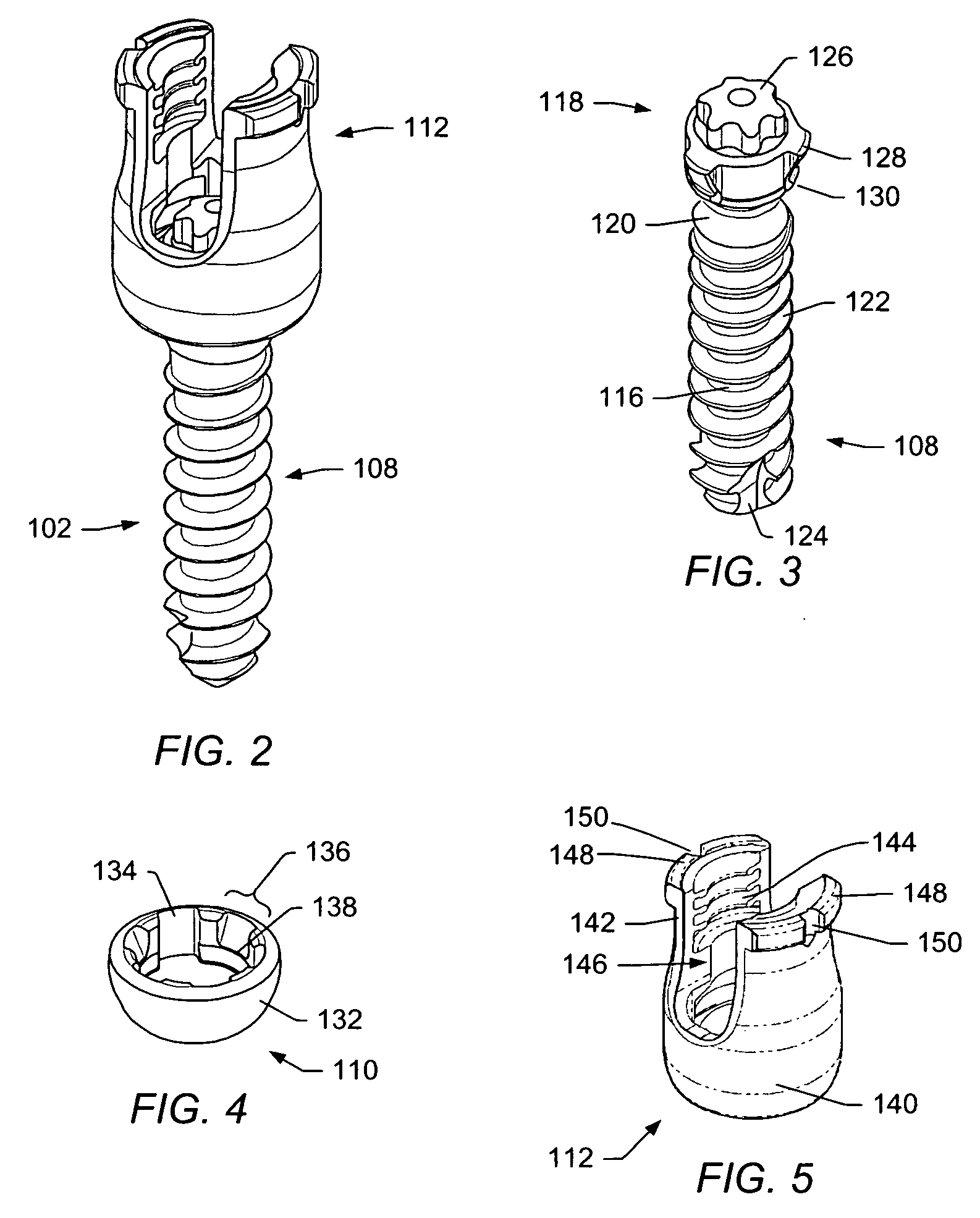
[0009] A spinal stabilization system may be used to achieve rigid pedicle fixation while minimizing the amount of damage to surrounding tissue. In some embodiments, a spinal stabilization system may be used to provide stability to two or more vertebrae. A spinal stabilization system may include an elongated member, two or more bone fastener assemblies, and / or a closure member.
[0011] During some spinal stabilization procedures, a spinal implant or other device may be inserted using an anterior approach, lateral approach or posterior approach. To stabilize the spinal implant or other device, a stabilization system may be installed using a posterior approach. In some embodiments, the spinal stabilization system may be installed using a minimally invasive surgical procedure where the stabilization system is installed through a small incision formed in the patient. During some surgical procedures, movement of vertebrae closer together may be desired to secure the position of an installed spinal implant or other device and / or to promote bone growth. During some surgical procedures, movement of vertebrae farther apart may be desired to provide a desired spacing between the vertebrae and / or to allow working room for manipulation of a device positioned between the vertebrae. An adjuster may be used with instruments used to install the spinal stabilization system to change the position of vertebrae coupled together by the spinal stabilization system. The adjuster may allow a closure member to be secured to a collar of the spinal stabilization system while a desired separation distance is maintained between the vertebrae.
[0013] In some embodiments, the adjuster may include an engagement mechanism. In a first position, the engagement mechanism may allow a first handle of the adjuster to translate towards or away from a second handle of the adjuster. In a second position, the engagement mechanism may inhibit translation of the first handle relative to the second handle. The engagement mechanism may facilitate coupling the adjuster and the driver to the first extender and the second extender. In embodiments where the adjuster is a compressor, the engagement mechanism may also allow a user to establish a separation distance between the driver and an end surface of the compressor. The established separation distance may allow the driver to rotate towards the compressor to allow for compression of the vertebral bodies.

Problems solved by technology

Degeneration may destabilize bone and affect surrounding structures.
For example, destabilization of a spine may result in alteration of a desired spacing between adjacent vertebrae.
Pressure applied to the nerves may cause pain and / or nerve damage.
Conventional procedures may result in trauma to the soft tissue, for example, due to muscle stripping.

Method used


Image

  • Instruments and methods for adjusting separation distance of vertebral bodies with a minimally invasive spinal stabilization procedure
  • Instruments and methods for adjusting separation distance of vertebral bodies with a minimally invasive spinal stabilization procedure
  • Instruments and methods for adjusting separation distance of vertebral bodies with a minimally invasive spinal stabilization procedure

Examples


Embodiment Construction

[0057] A spinal stabilization system may be installed in a patient to stabilize a portion of a spine. Spinal stabilization may be used, but is not limited to use, in patients having degenerative disc disease, spinal stenosis, spondylolisthesis, pseudoarthrosis, and / or spinal deformities; in patients having fracture or other vertebral trauma; and in patients after tumor resection. A spinal stabilization system may be installed using a minimally invasive procedure. An instrumentation set may include instruments and spinal stabilization system components for forming a spinal stabilization system in a patient and for facilitating compression or distraction of one or more vertebral bodies.

[0058] A minimally invasive procedure may be used to limit an amount of trauma to soft tissue surrounding vertebrae that are to be stabilized. In some embodiments, the natural flexibility of skin and soft tissue may be used to limit the length and / or depth of an incision or incisions needed during the ...


PUM


Abstract

A spinal stabilization system may be formed in a patient. In some embodiments, a minimally invasive procedure may be used to form a spinal stabilization system in a patient. Bone fastener assemblies may be coupled to vertebrae. Each bone fastener assembly may include a bone fastener and a collar. Extenders may be coupled to the collar to allow for formation of the spinal stabilization system through a small skin incision. The extenders may allow for alignment of the collars to facilitate insertion of an elongated member in the collars. An elongated member may be positioned in the collars and a closure member may be used to secure the elongated member to the collars. An adjuster may be used in conjunction with the extenders to change a separation distance between the bone fastener assemblies.

Description

BACKGROUND [0001] 1. Field of the Invention [0002] The present invention generally relates to instruments and methods used during a spinal stabilization procedure to manipulate vertebrae. More particularly, the present invention generally relates to spinal surgical procedures that use instruments and methods for adjusting a separation distance between adjacent vertebrae. [0003] 2. Description of Related Art [0004] Bone may be subject to degeneration caused by trauma, disease, and / or aging. Degeneration may destabilize bone and affect surrounding structures. For example, destabilization of a spine may result in alteration of a desired spacing between adjacent vertebrae. Alteration of a desired spacing between adjacent vertebrae may subject nerves that pass between vertebral bodies to pressure. Pressure applied to the nerves may cause pain and / or nerve damage. Maintaining the desired spacing between vertebrae may reduce pressure applied to nerves that pass between vertebral bodies. A ...

Claims


Application Information

Patent Timeline
Patent Type & Authority Applications(United States)
IPC IPC(8): A61F2/30
CPCA61B17/7091A61B17/7085A61B17/861A61B17/8866A61B17/8875A61B2017/0256A61B2019/307A61B17/025A61B17/16A61B17/1655A61B17/1757A61B17/7011A61B17/7032A61B17/7037A61B17/7079A61B17/8605
Inventor JONES, ROBERT J.FORTON, CHARLES R.
Owner ZIMMER BIOMET SPINE INC
Learn More