Substrate processing apparatus and substrate processing method drying substrate by spraying gas

a substrate processing and substrate technology, applied in the direction of drying machines with progressive movements, lighting and heating apparatus, furniture, etc., can solve the disadvantages of increasing the refined device characteristics, difficult to achieve reproducibility for preventing water marks, etc., to achieve stable and reliable drying of the surface of the substrate

Inactive Publication Date: 2006-06-15
DAINIPPON SCREEN MTG CO LTD
View PDF6 Cites 29 Cited by
  • Summary
  • Abstract
  • Description
  • Claims
  • Application Information

AI Technical Summary

Benefits of technology

[0010] The substrate processing apparatus can also completely remove a trace of moisture remaining on the surface of the substrate for stably and reliably drying the surface of the substrate.
[0012] The second nozzle sprays the gas to the same region as that on the substrate sprayed with the gas by the first nozzle, whereby the substrate processing apparatus can also completely remove a trace of moisture remaining on the surface of the substrate for stably and reliably drying the surface of the substrate.
[0014] The nozzle re-sprays the gas to the same region as that on the substrate sprayed with the gas by the nozzle, whereby the substrate processing apparatus can also completely remove a trace of moisture remaining on the surface of the substrate for stably and reliably drying the surface of the substrate.
[0016] Accordingly, an object of the present invention is to provide a substrate processing apparatus and a substrate processing method capable of stably and reliably drying the surface of a substrate.

Problems solved by technology

In a drying step subsequent to the rinse processing with deionized water, however, imperfect drying may result in the form of water marks, which are readily caused particularly when the substrate processing apparatus etches silicon (Si) or polysilicon forming the surface of the substrate with hydrofluoric acid due to partial exposure of a hydrophobic surface.
In view of the process, the conditional range for replacing the residual moisture with IPA is so narrow that reproducibility for prevention of water marks is hard to attain.
When the organic IPA is supplied to the surface of the substrate in the final drying step, increasingly refined device characteristics may disadvantageously be deteriorated.

Method used


Image

  • Substrate processing apparatus and substrate processing method drying substrate by spraying gas
  • Substrate processing apparatus and substrate processing method drying substrate by spraying gas
  • Substrate processing apparatus and substrate processing method drying substrate by spraying gas

Examples


first embodiment

1. First Embodiment

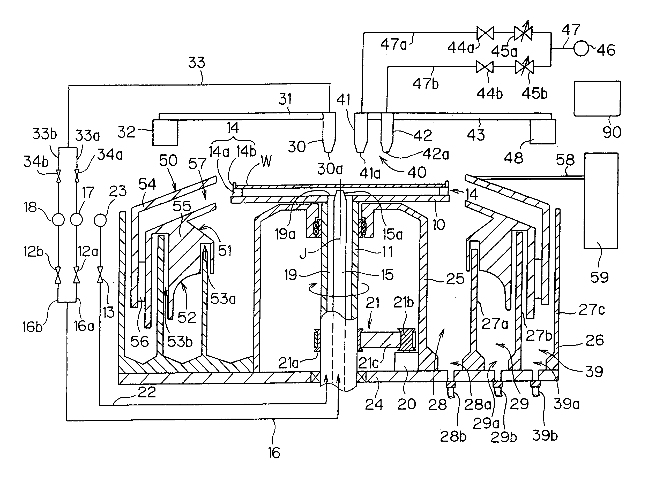
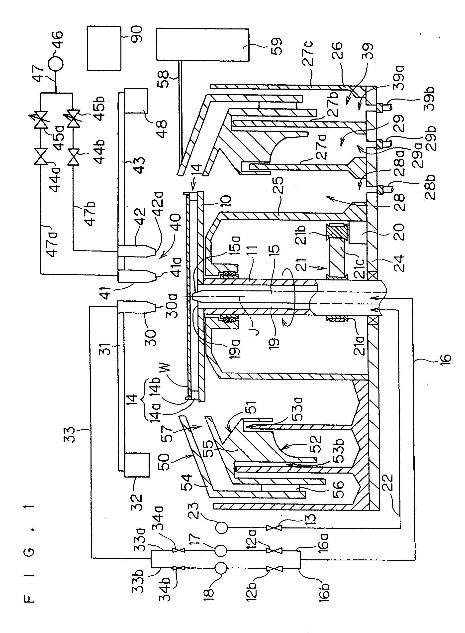
[0028]FIG. 1 is a longitudinal sectional view showing the structure of a substrate processing apparatus according to a first embodiment of the present invention. The substrate processing apparatus according to the first embodiment is a single-substrate type substrate processing apparatus performing cleaning processing etc. on a substrate W, and mainly comprises a spin base 10 holding the substrate W, a plurality of chuck pins 14 provided on the spin base 10, an electric motor 20 rotating the spin base 10, a processing solution nozzle 30 and a gas nozzle 40 provided above the spin base 10, a splash guard 50 enclosing the substrate W held by the spin base 10, a mechanism supplying a processing solution and gas to the substrate W held on the spin base 10 and a mechanism vertically moving the splash guard 50.

[0029] The spin base 10 substantially horizontally holds the substrate W thereon. This spin base 10 is a discoidal member having an opening on its center, and pr...

second embodiment

2. Second Embodiment

[0082] A second embodiment of the present invention is now described. FIG. 7 is a longitudinal sectional view showing the structure of a substrate processing apparatus according to the second embodiment. Referring to FIG. 7, members identical to those of the substrate processing apparatus according to the first embodiment are denoted by the same reference numerals, to omit redundant description. The structure of the substrate processing apparatus according to the second embodiment is different from that of the substrate processing apparatus according to the first embodiment in a set mode of a gas nozzle 40, and the remaining points of the former are identical to those of the latter. While FIG. 7 shows no processing solution nozzle 30 for convenience of illustration, the substrate processing apparatus according to the second embodiment has a processing solution nozzle 30 similar to that in the substrate processing apparatus according to the first embodiment.

[0083...

third embodiment

3. Third Embodiment

[0104] A third embodiment of the present invention is now described. FIG. 9 is a longitudinal sectional view showing the structure of a substrate processing apparatus according to the third embodiment. Referring to FIG. 9, members identical to those of the substrate processing apparatus according to the first embodiment are denoted by the same reference numerals, to omit redundant description. The structure of the substrate processing apparatus according to the third embodiment is different from that of the substrate processing apparatus according to the first embodiment in a set mode of a gas nozzle 40, and the remaining points of the former are identical to those of the latter.

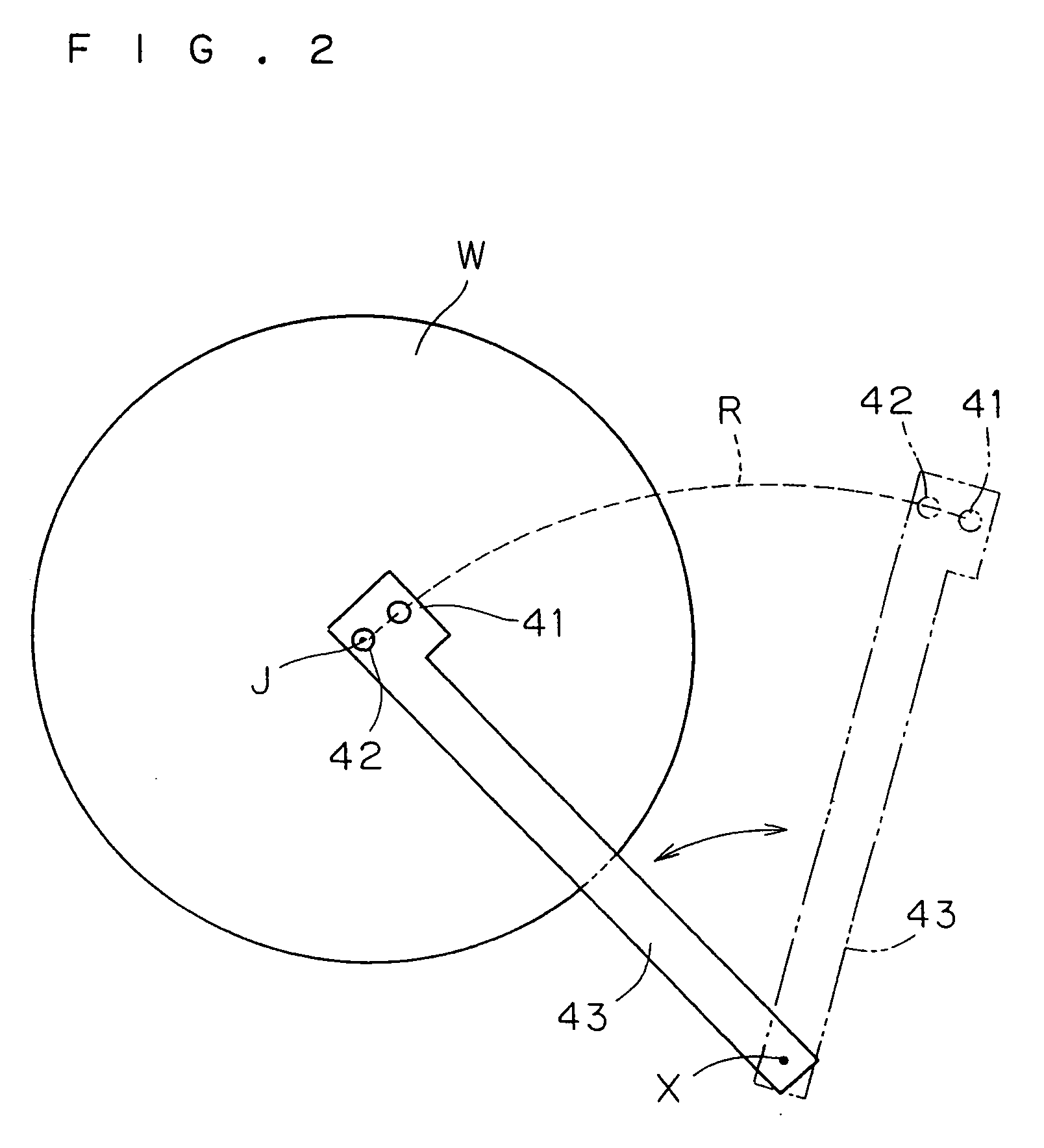
[0105] According to the third embodiment, the gas nozzle 40 is formed by a single nozzle. The gas nozzle 40 is fixed to a portion close to the forward end of a nozzle arm 43 while directing its discharge port 40a vertically downward. The base end of the nozzle arm 43 is coupled to the rot...


PUM


Abstract

A first gas nozzle and a second gas nozzle are fixedly provided in the vicinity of the forward end of a nozzle arm. The nozzle arm is rotated along a locus R while a substrate rinsed with deionized water is rotated, for discharging nitrogen gas from the first and second gas nozzles. Visible moisture is loosely expelled from the upper surface of the substrate by spraying the nitrogen gas from the first gas nozzle, and moisture slightly remaining on a fine pattern or the like can also be completely removed by spraying the nitrogen gas from the second gas nozzle to the same region of the substrate as that sprayed with the nitrogen gas by the first gas nozzle. Consequently, the surface of the substrate can be stably and reliably dried. Thus, a substrate processing apparatus capable of stably and reliably drying the surface of the substrate is provided.

Description

BACKGROUND OF THE INVENTION [0001] 1. Field of the Invention [0002] The present invention relates to a substrate processing apparatus, particularly a single-substrate type substrate processing apparatus, and a substrate processing method spraying gas to a semiconductor substrate, a glass substrate for a liquid crystal display, a glass substrate for a photomask, a substrate for an optical disk or the like (hereinafter simply referred to as “substrate”) for drying the substrate. [0003] 2. Description of the Background Art [0004] A single-substrate type substrate processing apparatus supplying a chemical solution such as hydrofluoric acid to a substrate while rotating the same for etching or cleaning the substrate generally performs rinse processing with deionized water after the chemical solution processing, followed by drying processing for removing the deionized water adhering to the substrate. In general, such a substrate processing apparatus dries the substrate by a technique of r...

Claims


Application Information

Patent Timeline
Patent Type & Authority Applications(United States)
IPC IPC(8): F26B3/00F26B21/00H01L21/00F26B5/14H01L21/304
CPCH01L21/67034Y10S134/902
Inventor IZUMI, AKIRA
Owner DAINIPPON SCREEN MTG CO LTD
Why Eureka
Try Eureka