Cathode for an electrode source

a cathode and electron source technology, applied in the manufacture of electrode systems, discharge tube main electrodes, electric discharge tubes/lamps, etc., can solve the problems of large number of manufacturing problems that still need to be fully resolved, high cost of cathodes, etc., to achieve high melting temperature and thermal stability, particularly useful characteristics, and good electrical conductivity

Inactive Publication Date: 2006-06-15
UNIVERSITY OF SURREY
View PDF3 Cites 11 Cited by
  • Summary
  • Abstract
  • Description
  • Claims
  • Application Information

AI Technical Summary

Benefits of technology

[0035] Carbon nanotubes have particularly useful characteristics for the cathode of the invention. In particular, they have very good electrical conductivity and relatively high melting temperature and thermal stability. This enables high electron current densities to be achieved.
[0036] Whilst the invention is not limited to carbon nanotubes or nanofibres produced by any particular method, and, as such, nanotubes and nanofibres produced by any conventional method can be used in the invention, the applicants have recognised that multi-wall carbon nanotubes grown at l

Problems solved by technology

However, this type of cathode is expensive and is yet to prove itself to be fully reliable.
A large number of manufacturing issues still need to be fully resolved.
This is costly to produce and difficult to maintain over a product lifetime of say 10 years or more without pumping, which is impractical for a flat panel display.
Similarly, damage to the tips can alter the characteristics of the electron source, increasing the required voltage and decreasing output.
The cathode and anode also need to be very close to one another, e.g. a few micrometres apart, which leads to problems with mass production.
Thermionic electron sources are typically cheap, easy to replace, and require less perfect vacuums to operate than field emission electron sources, although they tend to have a relatively short life.
In addition, the typical energy spread of the electrons they emit can b

Method used


Image

  • Cathode for an electrode source
  • Cathode for an electrode source
  • Cathode for an electrode source

Examples


Embodiment Construction

Thermionic Cathode

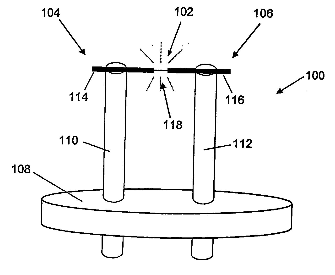
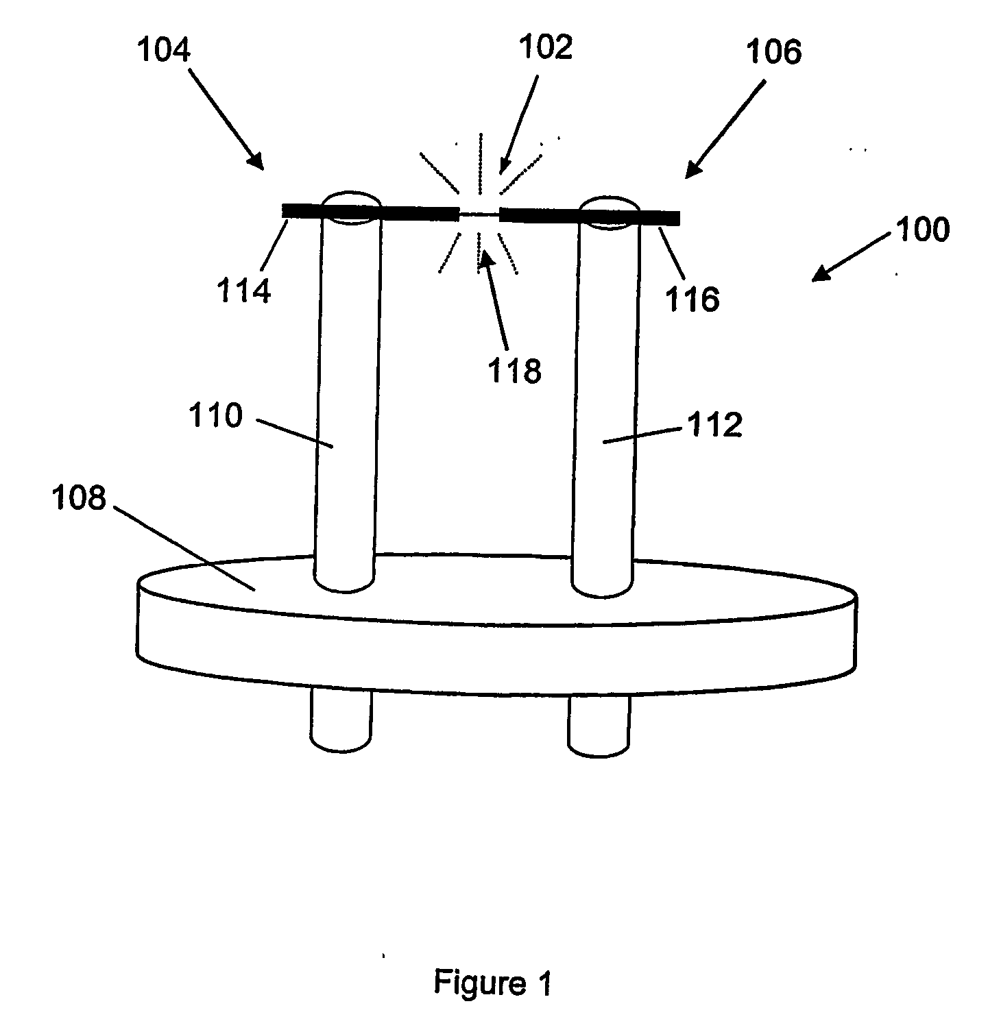
[0044] Referring to FIG. 1, a thermionic cathode 100 comprises an individual carbon nanotube 102 attached between two electrodes 104, 106. The electrodes 104, 106 are mounted on a substrate or, in this embodiment, attached to an insulating base 108. The electrodes 104, 106 each comprise a post 110, 112 and a carbon fibre 114, 116. The posts 110, 112 are each generally upright with respect to the base 108 and spaced part from one another by around 3 mm. The carbon fibres 114, 116 are attached to the ends of the posts 110, 112 distal from the base 108 and extend toward one another, substantially along a single axis. In this embodiment, the carbon fibres 114, 116 are each substantially orthogonal to the post 110, 112 to which they are attached and extend a roughly equal distance toward one another. So, the electrodes 104, 106 can be thought of as almost forming a goalpost shape, although the cross bar is divided into two parts (each of the carbon fibres 114, 116). T...


PUM


Abstract

A thermionic cathode (100) comprises an individual carbon nanotube (102) attached between two electrodes (104, 106). The electrodes (104, 106) each comprise a post (110, 112) and a carbon fibre (114, 116). A gap (118) narrower than the length of the nanotube (102) is provided between the two carbon fibres and the carbon nanotube (102) bridges the gap. This provides an extremely efficient thermionic cathode (100).

Description

FIELD OF THE INVENTION [0001] This invention relates to a cathode for an electron source and to a method of manufacturing such a cathode. A particular, but not exclusive, implementation of the invention concerns a cathode incorporating a carbon nanotube. BACKGROUND TO THE INVENTION [0002] Cathodes are currently used in electron sources for many applications, including television and computer displays for example. Currently, these displays are mostly either cathode ray tubes (CRTs) or flat panel liquid crystal displays (LCDs). CRTs typically use electron sources incorporating so-called thermionic cathodes. Thermionic cathodes operate by heating an element so that free electrons conceptually “boil” off the element. An electric field between the cathode and an anode then accelerates the electrons away from the cathode. LCDs of course do not require an electron source. However, there are a variety of new flat panel display technologies coming into use that do require electron sources, i...

Claims


Application Information

Patent Timeline
IPC IPC(8): H01L31/111H01J1/13H01J1/304H01J9/02H01J9/04
CPCB82Y10/00H01J1/304H01J9/025H01J2201/30469
Inventor COX, DAVID CHRISTOPHERFORREST, ROY DUNCANSILVA, SEMBUKUTIARACHILAGE RAVI
Owner UNIVERSITY OF SURREY
Why Eureka
Try Eureka