
Lithographic apparatus and method for optimizing illumination using a photolithographic simulation

a lithographic apparatus and simulation technology, applied in the field of optimizing illumination in the lithographic apparatus, can solve the problems of reducing the depth of focus, unable to provide the desired pattern architecture with similar accuracy, speed and economic productivity, and the resolution limit of currently available lithographic techniques is reached

Inactive Publication Date: 2006-06-15
ASML NETHERLANDS BV
View PDF22 Cites 109 Cited by
  • Summary
  • Abstract
  • Description
  • Claims
  • Application Information

AI Technical Summary

Benefits of technology

[0048] Although specific reference may be made in this text to the use of the apparatus according to the invention in the manufacture of ICs, it should be explicitly understood that such an apparatus has many other possible applications. For example, it may be employed in the manufacture of integrated optical systems, guidance and detection patterns for magnetic domain memories, liquid crystal display panels, thin film magnetic heads, etc. It should be appreciated that, in the context of such alternative applications, any use of the terms “reticle”, “wafer” or “die” in this text should be considered as being replaced by the more general terms “mask”, “substrate” and “target portion”, respectively.

Problems solved by technology

At present, no alternative technology provides the desired pattern architecture with similar accuracy, speed, and economic productivity.
As the semiconductor industry moves into the deep submicron regime, the resolution limit of currently available lithographic techniques is being reached due to a decrease in the depth of focus, difficulty in the design of lenses and complexities in the lens fabrication technology.
Such an approach results in a significant loss in intensity available to the mask, lowering throughput and making the approach less than desirable.
Additionally, the four circular openings need to be designed specifically for certain mask geometry and pitch and do not improve the performance of other geometry sizes and spacings.
Yet, given the cost and time to perform experiments in a semiconductor fabrication facility (fab), the approach that would consist of testing these options across the board to develop a robust process is simply unrealistic.
As the product cycle times in the semiconductor field are relatively short, severe limitations are put on the amount of time that can be spent on research and development for each new product line or manufacturing process.

Method used


Image

  • Lithographic apparatus and method for optimizing illumination using a photolithographic simulation
  • Lithographic apparatus and method for optimizing illumination using a photolithographic simulation
  • Lithographic apparatus and method for optimizing illumination using a photolithographic simulation

Examples


Embodiment Construction

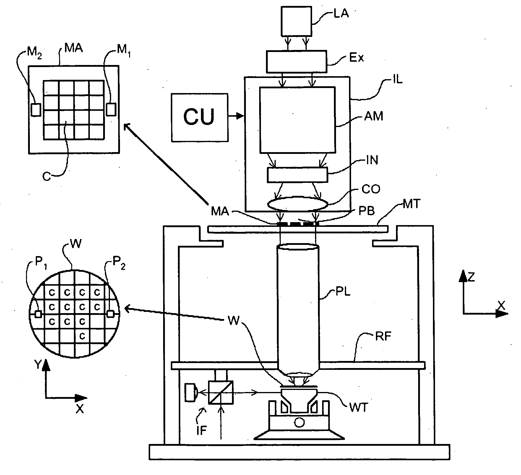
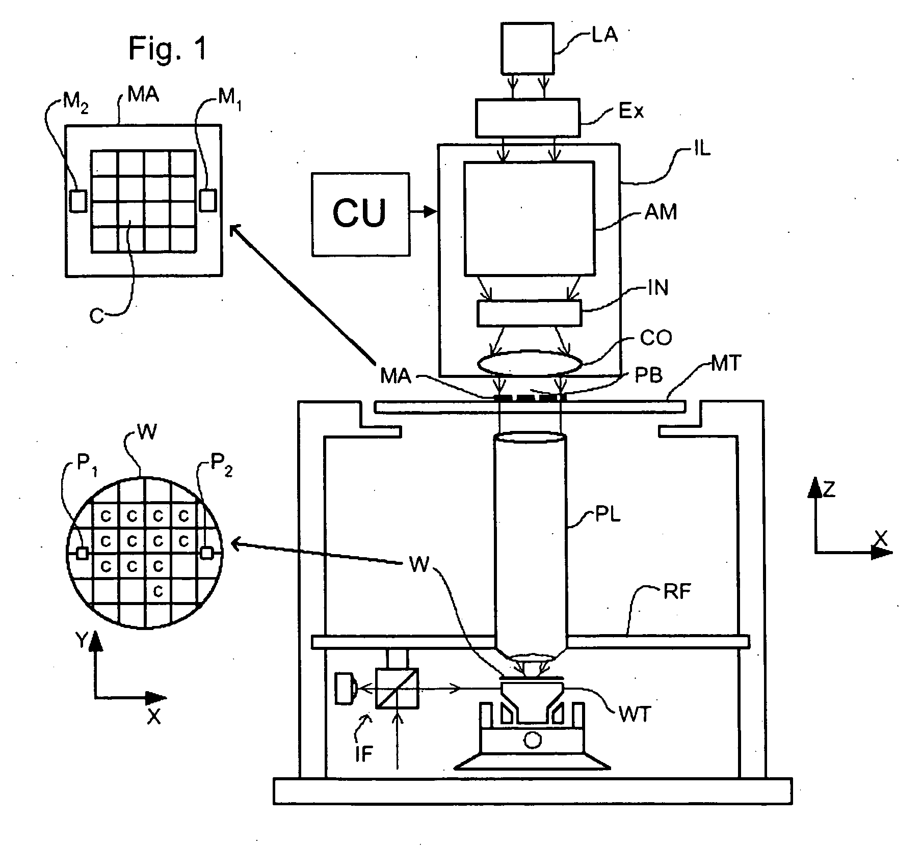
[0136]FIG. 1 schematically depicts a lithographic projection apparatus 1 according to an embodiment of the invention. The apparatus includes a radiation system Ex, IL constructed and arranged to supply a projection beam PB of radiation (e.g., UV or EUV radiation, such as, for example, generated by an excimer laser operating at a wavelength of 248 nm, 193 nm or 157 nm, or by a laser-fired plasma source operating at 13.6 nm). In this embodiment, the radiation system also comprises a radiation source LA. The apparatus also includes a first object (mask) table MT provided with a mask holder constructed and arranged to hold a mask MA (e.g., a reticle), and connected to a first positioning device PM (not shown) to accurately position the mask with respect to a projection system or lens PL; a second object (substrate) table WT provided with a substrate holder constructed and arranged to hold a substrate W (e.g., a resist-coated silicon wafer), and connected to a second positioning device P...


PUM

PropertyMeasurementUnit
thresholdaaaaaaaaaa
wavelengthaaaaaaaaaa

Abstract

A method of configuring a transfer of an image of a patterning device pattern onto a substrate with a lithographic apparatus. The method includes determining an intermediate illumination arrangement parameter and an intermediate patterning device parameter by varying an initial illumination arrangement parameter and an initial patterning device parameter using a calibrated model until the calculated image of the pattern printed on the substrate is within predetermined specification; calculating a metric that represents a lithographic response of the printed pattern over a process range, where the pattern would be imaged with the intermediate illumination arrangement and patterning device parameters over the process range, and depending on a result of the metric, adjusting the initial patterning device and illumination arrangement parameters.

Description

[0001] This application is a continuation-in-part of co-pending U.S. patent application Ser. No. 10 / 773,397, filed Feb. 9, 2004, entitled, “Lithographic Apparatus and Method for Optimizing an Illumination Source Using Photolithographic Simulations,” which is a continuation-in-part of U.S. patent application Ser. No. 10 / 361,831, filed Feb. 11, 2003, now U.S. Pat. No. 6,839,125, entitled “Method for Optimizing an Illumination Source Using Full Resist Simulation and Process Window Metric,” and co-pending U.S. patent application Ser. No. 10 / 716,439, filed Nov. 20, 2003, entitled “Lithographic Apparatus and Method for Optimizing an Illumination Source Using Isofocal Compensation.” The contents of these applications are incorporated herein in their entirety by reference.BACKGROUND [0002] 1. Field of the Invention [0003] The present invention relates to a method for optimizing illumination in a lithographic apparatus. More specifically, the invention relates to a method for optimizing illu...

Claims


Application Information

Patent Timeline
Patent Type & Authority Applications(United States)
IPC IPC(8): G03B27/52G03F7/20
CPCG03F7/70108G03F7/705
Inventor HANSEN, STEVEN GEORGE
Owner ASML NETHERLANDS BV
Learn More