
Lithographic apparatus, device manufacturing method, and device manufactured thereby

a technology of lithographic apparatus and manufacturing method, applied in the direction of photomechanical apparatus, instruments, optics, etc., can solve the problems of large fabrication facilities, large use of separate tools, and complex handling systems for loading, unloading,

Active Publication Date: 2006-06-22
ASML NETHERLANDS BV
View PDF24 Cites 34 Cited by
  • Summary
  • Abstract
  • Description
  • Claims
  • Application Information

AI Technical Summary

Benefits of technology

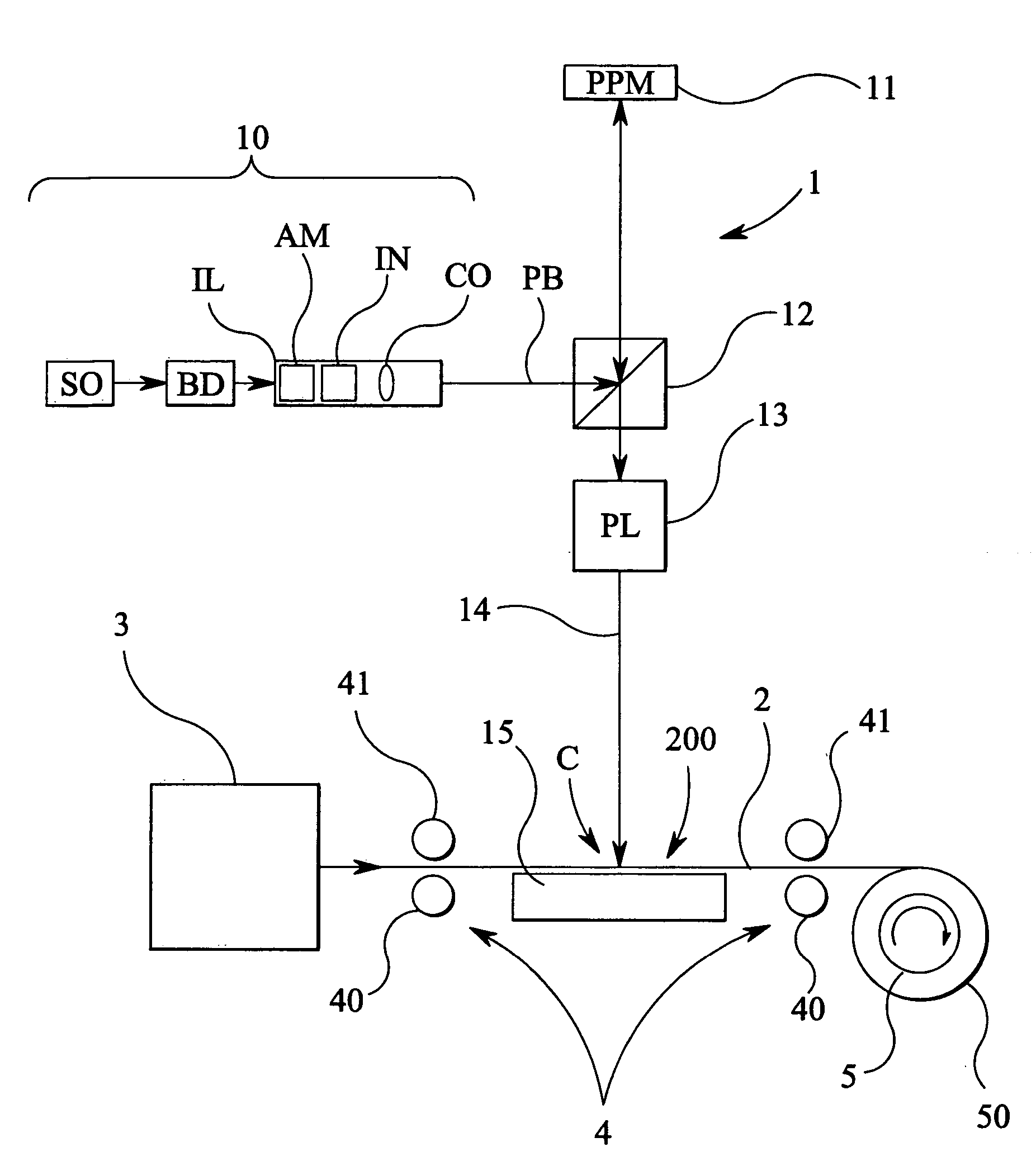
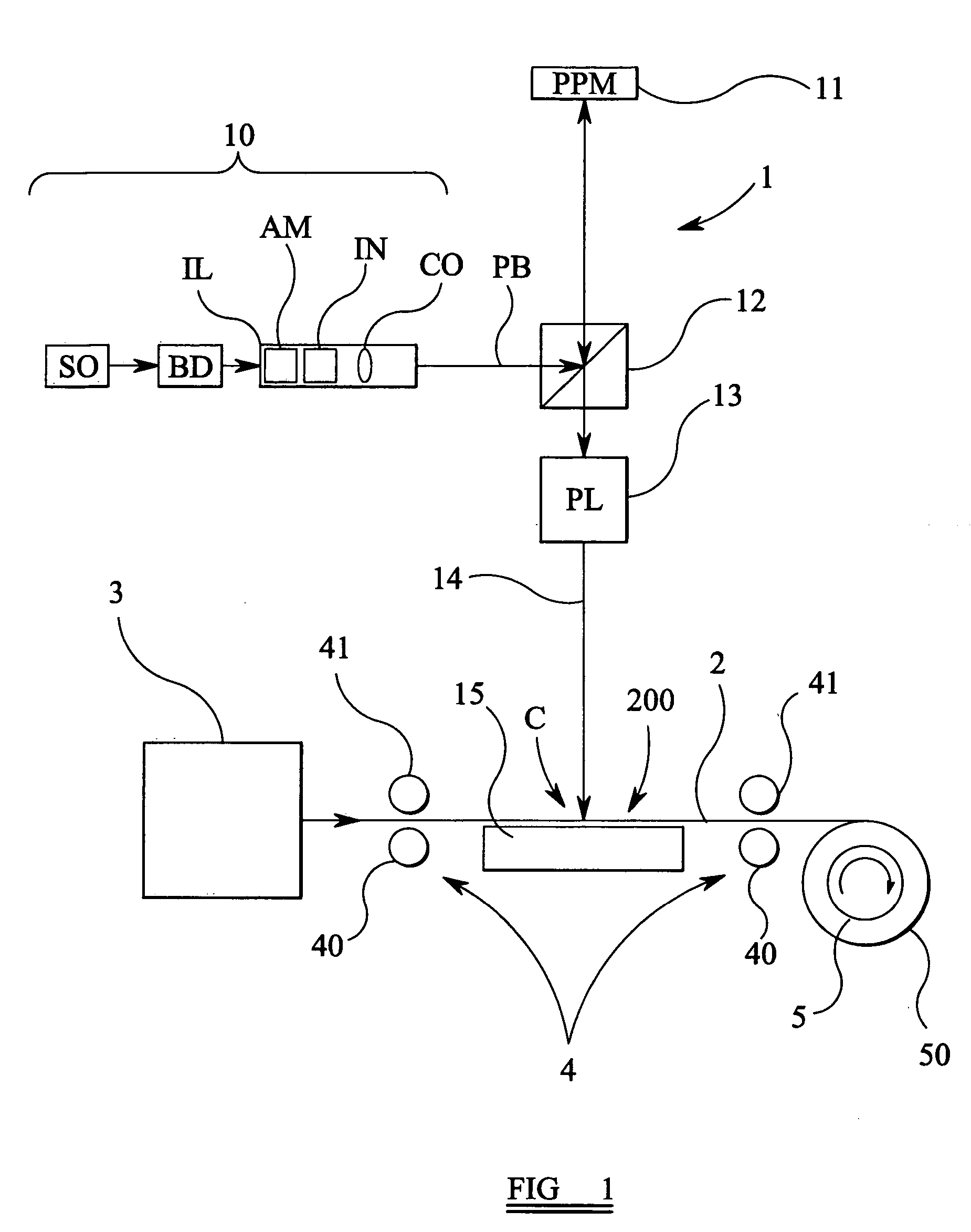
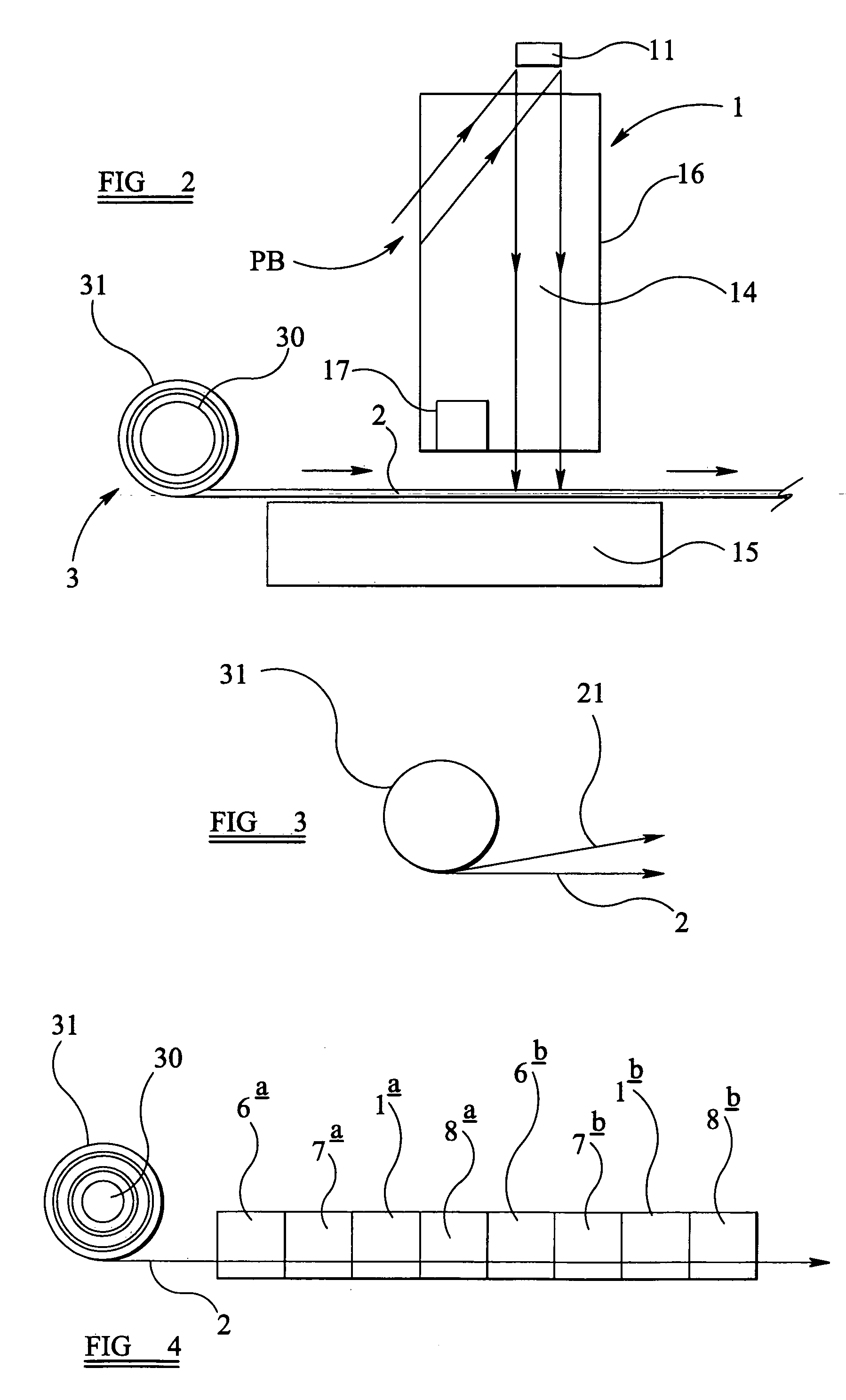
[0010] According to a further embodiment, the substrate conveying system is arranged to convey the, or each, outputted unbroken length of substrate continuously from the substrate supply and past the projection system (i.e., it conveys each individual length in an uninterrupted manner from the supply past the projection system). In other words, it can be arranged to move the length(s) progressively, without interruption, past the projection system, thereby providing a smooth and continuous feed. The conveying system transports the, or each, length along a linear path.
[0012] By supplying substrate continuously from a roll, a greater throughput can be achieved compared with batch processing. The exposed substrate can be collected on another reel (a take-up reel) for transport to other processing stages, or alternatively a number of stages can be arranged in series to give comprehensive in-line processing. This enables the area required for the fabrication system as a whole to be greatly reduced, in addition to improving production rate and reducing the substrate area tied up as work in progress. Embodiments of the invention can thus provide roll to roll “printing” (i.e., patterning). The substrates in certain examples can be rolls of plastic (e.g., organic sheets) or glass, and can be supplied continuously via an appropriate feed-through arrangement, to and through the lithographic stage or stages.
[0015] In embodiments, the lithographic apparatus further includes a detection system arranged to detect alignment marks on the continuous length, or lengths, of substrate. The detection system can be arranged to detect at least two rows of alignment marks extending along the continuous length of substrate. In certain examples, the detection system is arranged to output a detection signal in response to detecting the alignment marks, the lithographic apparatus further comprising a controller arranged to provide a control signal to the array of controllable elements, the controller being arranged to receive the detection signal and to determine the control signal according to the detection signal (e.g., the controller can adjust or adapt the control signal according to the detection signal). By appropriate arrangement of a detection system and the alignment marks, the apparatus can thus detect distortions such as thermal expansions and contractions of the substrate surface as the substrate is moving along, and then adjust the control of the array (or arrays) of controllable elements accordingly so that the projected pattern is correctly in register with the substrate surface. The system can thus adapt to factors which would otherwise have led to errors in the positioning of the projected beam pattern, and furthermore can perform these corrections without having to interrupt the motion (feed) of substrates through the lithographic apparatus.

Problems solved by technology

The use of separate tools and the need for complex handling systems for loading, unloading, and inter-tool transport have also required large fabrication facilities.

Method used


Image

  • Lithographic apparatus, device manufacturing method, and device manufactured thereby
  • Lithographic apparatus, device manufacturing method, and device manufactured thereby
  • Lithographic apparatus, device manufacturing method, and device manufactured thereby

Examples


Embodiment Construction

Overview and Terminology

[0039] Although specific reference can be made in this text to the use of lithographic apparatus in the manufacture of integrated circuits (ICs), it should be understood that the lithographic apparatus described herein can have other applications, such as, for example, the manufacture of DNA chips, micro-electromechanical systems (MEMS), micro-optical-electromechanical systems (MOEMS), integrated optical systems, guidance and detection patterns for magnetic domain memories, flat panel displays, thin-film magnetic heads, micro and macro fluidic devices, etc. The skilled artisan will appreciate that, in the context of such alternative applications, any use of the terms “wafer” or “die” herein can be considered as synonymous with the more general terms “substrate” or “target portion,” respectively. The substrate referred to herein can be processed, before or after exposure, in for example a track (e.g., a tool that typically applies a layer of resist to a subs...


PUM


Abstract

Substrate processing apparatus includes a lithographic apparatus which comprises an illumination system for supplying a projection beam of radiation, an array of individually controllable elements serving to impart the projection beam with a pattern in its cross-section, and a projection system for projecting the patterned beam onto a target portion of a substrate. The processing apparatus also includes a substrate supply arranged to output at least one unbroken length of substrate, and a substrate conveying system arranged to convey each outputted unbroken length of substrate from the substrate supply and past the projection system such that the projection system is able to project the patterned beam onto a series of target portions along each unbroken length of substrate. In certain embodiments, long lengths of substrate are supplied from a roll, but alternatively a series of separate sheets can be supplied.

Description

BACKGROUND OF THE INVENTION [0001] 1. Field of the Invention [0002] The present invention relates to substrate processing apparatus incorporating a lithographic apparatus and a device manufacturing method. [0003] 2. Related Art [0004] A lithographic apparatus is a machine that applies a desired pattern onto a target portion of a substrate (e.g., a workpiece, an object, a display, etc.). The lithographic apparatus can be used, for example, in the manufacture of integrated circuits (ICs), flat panel displays, and other devices involving fine structures. In a conventional lithographic apparatus, a patterning means, that is alternatively referred to as a mask or a reticle, can be used to generate a circuit pattern corresponding to an individual layer of the IC (or other device), and this pattern can be imaged onto a target portion (e.g., comprising part of a die, one die, or several dies) on a substrate (e.g., a silicon wafer or glass plate) that has a layer of radiation-sensitive mater...

Claims


Application Information

Patent Timeline
IPC IPC(8): G03B27/42
CPCG03F7/70291G03F7/70791
Inventor LOF, JOERIFLUIT, JEROENLUTTIKHUIS, BERNARDUS ANTONIUS JOHANNESSPIT, PETER
Owner ASML NETHERLANDS BV
Learn More