
Flammability tester

a technology of flammability tester and flammability temperature, which is applied in the field of flammability tester, can solve the problems of poor mass transfer, relatively inefficient conversion of fuel gas, and obtained sample ignition temperature, and achieve the effects of quick and accurate measurement, and quick and accurate measuremen

Inactive Publication Date: 2006-06-22
US DEPT OF TRANSPORTATION
View PDF4 Cites 23 Cited by
  • Summary
  • Abstract
  • Description
  • Claims
  • Application Information

AI Technical Summary

Benefits of technology

[0018] Accordingly, it is an object of the present invention to provide a device and method for quickly and accurately measuring flammability properties of milligram and centigram samples of combustible materials.
[0019] It is also an object of the present invention to provide a device and method for quickly and accurately measuring the heat release rates of milligram and larger samples of combustible materials without the need to simultaneously measure the mass loss rate of the sample and the heat of combustion of the fuel gases.
[0020] It is also an object of the present invention to provide a device and method for accurately measuring the heat release rates of milligram and larger samples of combustible materials without the need to mathematically correct (deconvolute) the oxygen consumption signal to account for diffusion in the combustion chamber.

Problems solved by technology

In either case, the ignition temperature of the sample is obtained by a tedious and time consuming bracketing procedure of raising or lowering the furnace / glow wire temperature until incipient ignition is observed.
In flaming mode, a fire calorimeter is used (see Heat Release Rate, above) but the heat of combustion of the fuel gases so measured is an effective value that is less than the total amount that is available because the combustion reactions in the flame are relatively inefficient at converting fuel gases to stable combustion products (water, carbon dioxide, and acid gases) because the fuel gases and air mix by diffusion.
However, the Lyon & Walters device was later found to have poor mass transfer between the pyrolysis and combustion stages and the Lyon device had large signal noise associated with the mathematical procedure (deconvolution) used to correct for excessive mixing in the long (12 foot, coiled) combustion chamber that precluded an accurate determination of the heat release rate or ignition temperature of the sample.
Consequently, these are not the methods of choice for accurately and quickly measuring the fire properties of limited quantities of materials.
Consequently, although the ignition temperature, the burning rate, the heat release rate, and the heat of combustion of the fuel gases of a combustible material can be separately determined using (at least) three devices and a large mass (kilogram) of sample, the process is expensive, time consuming and inefficient for materials research or quality control testing where small samples are all that is typically available
However, only the methods that measure or reproduce the mass loss rate of the sample can determine heat release rate of an individual material particle (specific heat release rate) as it occurs at a burning surface in a fire.
Because the rate of mass loss at the burning surface is a relatively slow process in comparison to the gas phase combustion reactions in the flame, the heat release in a fire is simultaneous with the mass loss (fuel generation) rate of the sample.
Consequently, unless the evolved gas measurement is synchronized with the sample mass loss in a laboratory test, the ignition temperature and heat release rate as they occur in a fire cannot be measured.
However, the oxygen consumption signal used to calculate heat release rate and heat release was distorted in the pyrolyzer by mixing and dilution of fuel gases with purge gases, and in the combustor by diffusion of combustion products.
The combination of errors arising from the two separate mixing processes (i.e., mixing and dilution in the pyrolyzer and diffusion in the combustor) severely distorted the heat release history and precluded an accurate determination of heat release rate by this technique.
However, the mathematical deconvolution procedure introduced considerable noise (uncertainty) in the heat release rate history—both in time and in magnitude.
Moreover, this heat release rate calorimeter was not easily adaptable to measurements of liquids, had no capability for directly measuring sample temperature, and the transition between the separate pyrolyzer and combustor introduced an abrupt temperature drop that delayed and distorted the continuous passage of the products of pyrolysis into the combustor.
The greatest source of error, however, proved to be the measurement uncertainty associated with the mathematical deconvolution to correct for diffusional mixing in the long (12 foot) combustion tube which had an internal volume of 100 cm3.
Previous calorimeters, including the calorimeter described in U.S. Pat. No. 6,464,391, measure and control the temperature of the pyrolyzer, not the sample, and therefore cannot be used to determine the ignition temperature because thermal lag during heating causes unknown differences between the sample temperature and the measured pyrolyzer temperature.

Method used


Image

  • Flammability tester
  • Flammability tester
  • Flammability tester

Examples


Embodiment Construction

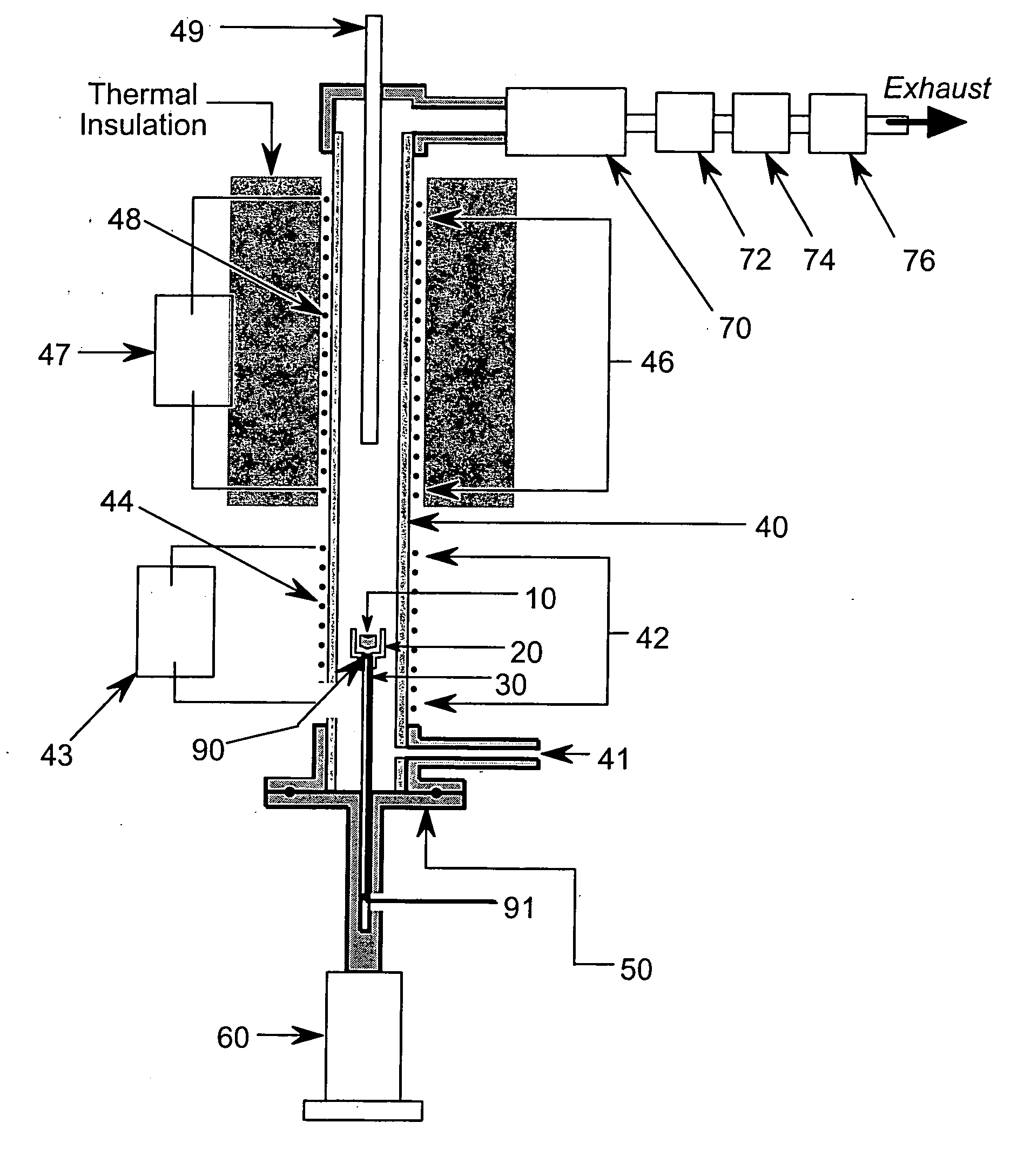
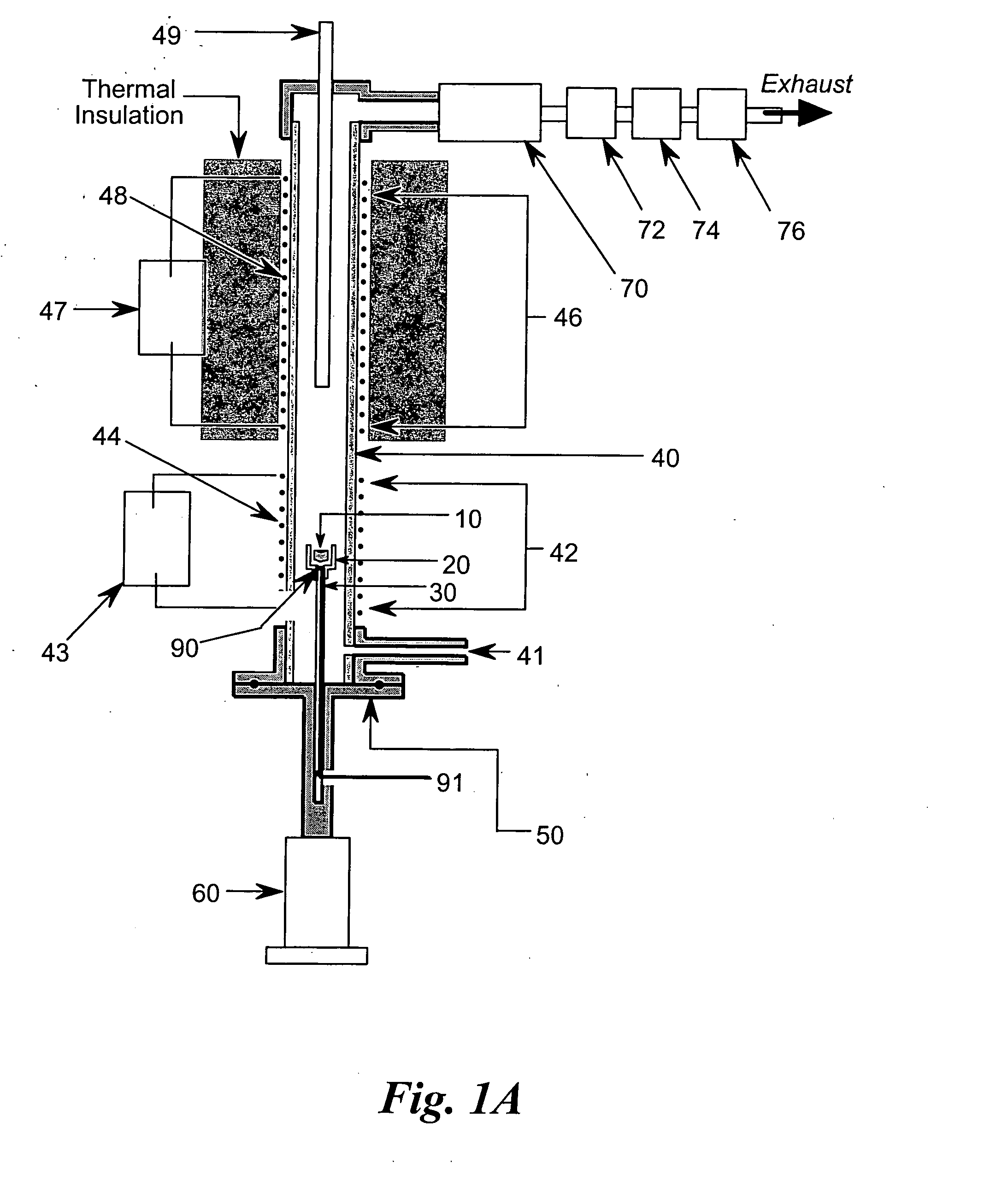
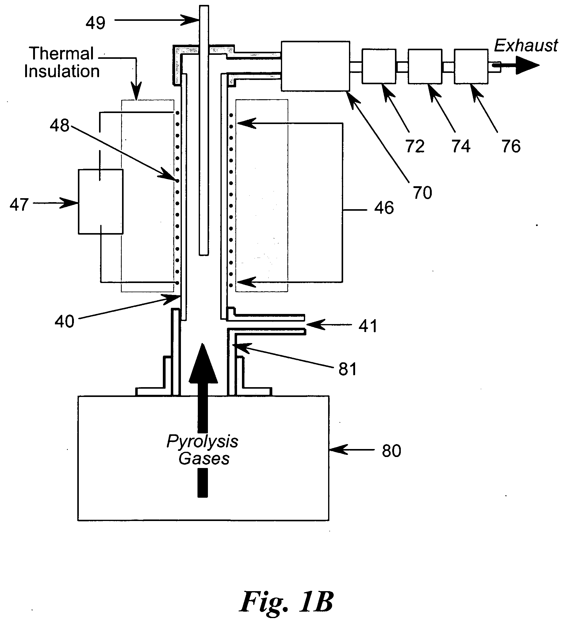
[0038] In the flammability tester of FIG. 1A, the test sample 10 is placed in sample cup 20 located at the top of sample mounting post 30 inserted into ceramic tube 40 using flange and sample mounting post assembly 50 attached to actuator 60. While the present embodiment uses a nonporous ceramic tube with an internal diameter of approximately one centimeter, other suitable high-temperature capable and corrosion resistant materials, such as Inconel™, Monel™, etc., and other convenient diameters would also suffice. The lower section of ceramic tube 40 constitutes the pyrolysis chamber, or pyrolyzer 42 of the tester, while the upper section of ceramic tube 40 constitutes the combustion chamber, or combustor 46 of the tester. In the present embodiment, the combustor 46 is approximately eight inches (20 cm) long. Sample actuator 60 positions sample 10 into ceramic tube 40 by sliding sample cup 20 on mounting post 30 upward into ceramic tube 40 until flange and sample mounting post assemb...


PUM


Abstract

A flammability tester for samples in the milligram range. A tube with a lower pyrolyzing region, or pyrolyzer, contains a sample that is heated to thermally degrade in the absence of oxygen, or pyrolyzed, to produce fuel gases. An inert gas carries the fuel gases to an upper combustion region, or combustor, where oxygen is measured into the gas flow containing the inert gas and fuel gases. Combustion of the fuel gases occurs at a temperature where the reaction time for almost all of the fuel gases is at or below 10 seconds. Under these conditions, the combustor volume need for complete combustion is small, permitting the fuel gases to be oxidized as they are liberated and travel from the pyrolyzer into the combustor in what is essentially sequential flow. Complete combustion in such a small volume produces a large decrease in the oxygen content of the gases emerging from the combustor, allowing the use of a simple inexpensive oxygen analyzer to measure the oxygen content of the gases emerging from the combustor. Oxygen depletion can be used to determine flammability parameters of the sample. The tester can be fitted with a thermometer to measure the combustion temperature of the pyrolyzed sample. The tester may also be configured to use a carbon dioxide analyzer to measure additional flammability parameters. The tester may also be combined with a separate thermogravimetric analyzer to yield further flammability parameters where the mass loss rate of the pyrolyzing sample is needed.

Description

STATEMENT OF GOVERNMENT INTEREST [0001] The present invention may be made or used by or for the Government of the United States without the payment of any royalties thereon.FIELD OF THE INVENTION [0002] The present invention relates generally to calorimeters, and more specifically to calorimeters used to measure multiple flammability parameters of combustible materials, including ignition temperature, burning rate, heat release rate, and heat of combustion, using small samples. A flammability tester that simultaneously measures multiple flammability parameters is derived from such calorimeters and is useful for quickly and accurately testing milligram and larger samples of combustible materials. BACKGROUND [0003] In a fire, the temperature at which a combustible material ignites (the ignition temperature), the rate of mass loss as the material subsequently burns (the burning rate), the rate at which the material releases heat in flaming combustion (heat release rate), and the maximu...

Claims


Application Information

Patent Timeline
IPC IPC(8): G01N25/00
CPCG01N25/50G01N25/00
Inventor LYON, RICHARD E.
Owner US DEPT OF TRANSPORTATION
Learn More