Extreme ultraviolet light source and extreme ultraviolet light source target
What is AI technical title?
AI technical title is built by Patsnap AI team. It summarizes the technical point description of the patent document.
a technology of ultraviolet light source and target, which is applied in the direction of photomechanical equipment, instruments, nuclear engineering, etc., to achieve the effect of preventing the sublimation of fros
Active Publication Date: 2006-06-22
OSAKA UNIV
View PDF7 Cites 20 Cited by
Summary
Abstract
Description
Claims
Application Information
AI Technical Summary
This helps you quickly interpret patents by identifying the three key elements:
Problems solved by technology
Method used
Benefits of technology
Benefits of technology
[0007] The present invention was made in order to solve the above problems and it is an object of the present invention to provide an extreme ultraviolet light source in which extreme ultraviolet light can be emitted with high emission efficiency, and in which the generation of debris is prevented, and to provide a target used in the extreme ultraviolet light source.
[0010] According to the extreme ultraviolet light source target in the present invention, since the laser absorption region and the extreme ultraviolet light emission region are set closer in space, the loss of energy that is absorbed in the laser absorption region when the target is irradiated with the laser beam is reduced while the energy is transported to the extreme ultraviolet light emission region. Thus, the emission efficiency of the extreme ultraviolet light can be enhanced. Furthermore, when the laser absorption region and the extreme ultraviolet light emission region overlap in space, the intensity of irradiating laser, or the amount of input energy, can be minimized, and the emission efficiency of the extreme ultraviolet light can be further enhanced.
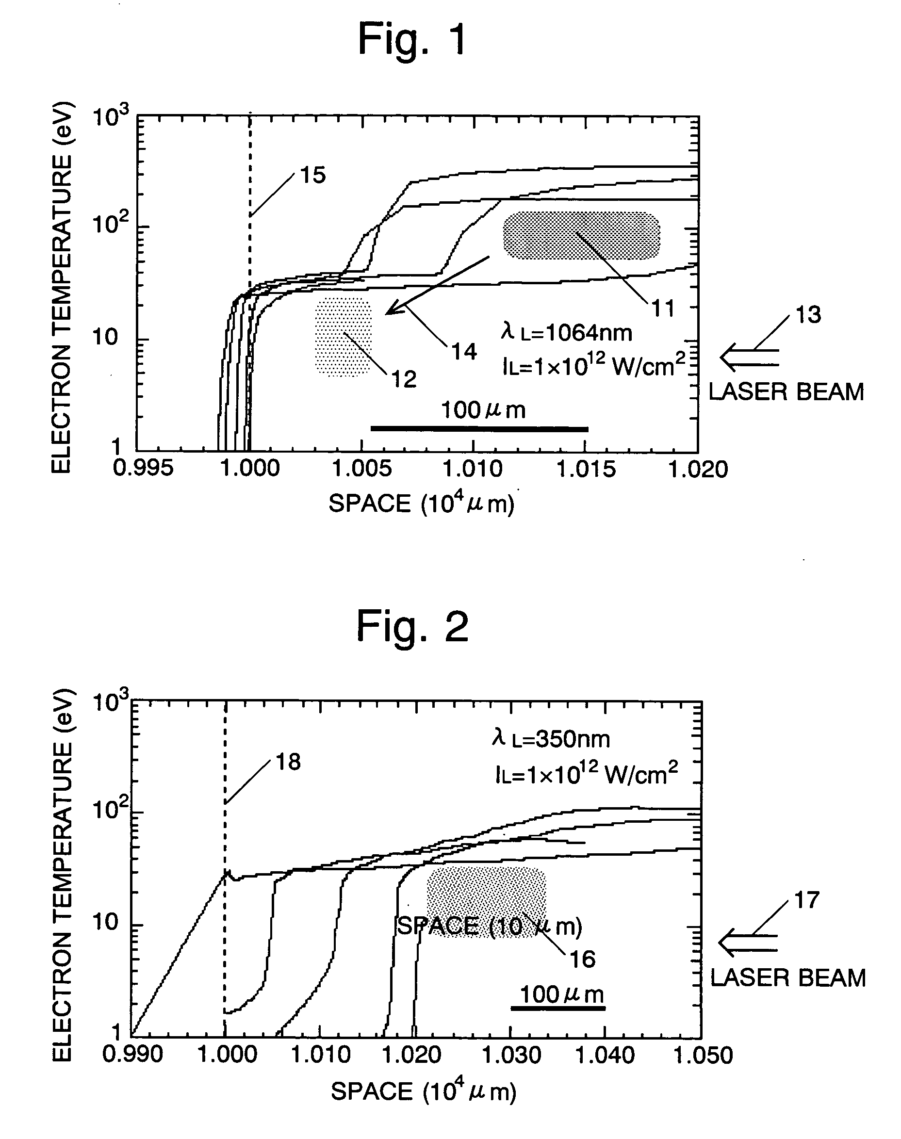
[0011] As a method of making the distance between the laser absorption region and the extreme ultraviolet light emission region smaller than before, or of making them overlap, the inventors of the present invention devised adjusting the density of the target. When the plasma is irradiated with the laser beam, the energy of the laser beam is absorbed in the plasma when the density of the plasma is within a predetermined range corresponding to the wavelength of the laser beam. The density of the plasma generated when the target is irradiated with the laser beam depends on the density of the target. Therefore, when the density of the target is appropriately adjusted, the region in which the plasma density is within the predetermined range, i.e. the laser absorption region, can be moved. Meanwhile, the extreme ultraviolet light is emitted in the region where the plasma is within a range of a predetermined electron temperature, and the predetermined electron temperature condition is not changed by a change in the density of the target. Therefore, by setting the density of the target appropriately, the laser absorption region and the extreme ultraviolet light emission region can be brought closer, or can overlap with each other.
[0022] As the density of the target is decreased, the target is prevented from dispersing as particles without generating plasma, or debris is prevented from being generated.
[0033] It is preferable that this system further comprises a bladed wheel rotatably fixed to the hopper just above the outlet and having a plurality of blades which radiate outward, and the hopper is formed cylindrically just above the outlet so as to surround the bladed wheel. In this constitution, an appropriate amount of the frost is discharged from the hopper in accordance with rotation of the bladed wheel. In addition, when a rotation axis of the bladed wheel is hollowed and the cooling material passes through it, it is preferable because sublimation of the frost is prevented.
Problems solved by technology
However, conventional targets have the following problem.
Method used
Image
Click on the blue label to locate the original text in one second.
Reading with bidirectional positioning of images and text.
Examples
first embodiment
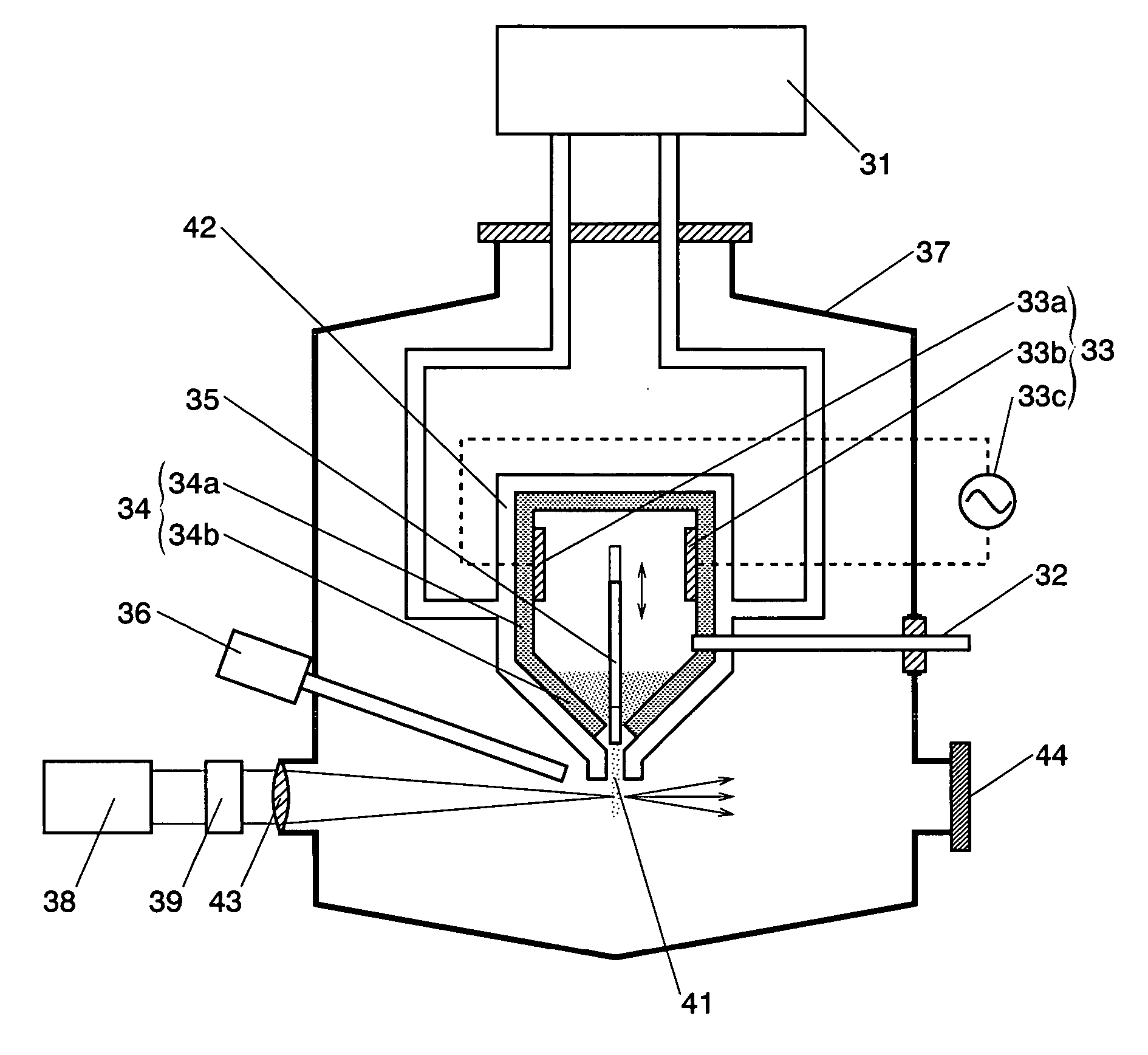
[0050] Next, a description will be made of an extreme ultraviolet light generating system using a target made of frost according to a second aspect. FIG. 5 is a vertical sectional view showing the extreme ultraviolet light source system according to this embodiment. The system comprises a freezing machine 31, a gas injection pipe 32, a heater 33, a hopper 34, a push-out rod 35, a monitor 36, a vacuum chamber 37, a high-output pulse laser beam generator 38, and a wavelength converter 39.
[0051] The hopper 34 is fixed in the vacuum chamber 37 and comprises a cylindrical body part 34a of an upper part and a conical guide part 34b of a lower part. Both body part 34a and guide part 34b are made of an insulating material such as a glass, a ceramics and the like. An outlet 41 through which the frost is discharged is provided at a lower end of the hopper 34. In addition, a pipe 42 in which a cooling medium such as liquid helium circulates along a wall surface is provided around the hopper 34...
second embodiment
[0056]FIG. 6 is a vertical sectional view showing an extreme ultraviolet light generating system using the target made of the frost in the second aspect according to a FIG. 7 is a sectional view taken along line A-A in FIG. 6.
[0057] The system includes a freezing machine 31, a gas injection pipe 32, a heater 33, a hopper 34, a monitor 36, a vacuum chamber 37, a high-output pulse laser beam generator 38 and a wavelength converter 39, and the components other than the heater 33 and the hopper 34 are the same as those in the extreme ultraviolet light generating system according to the first embodiment. In addition to the above components, a bladed wheel 51 is provided in the present embodiment. Only the bladed wheel, the heater 33 and the hopper 34 will be described hereinafter.
[0058] The heater 33 has three pairs of discharge electrodes 331a-331b, 332a-332b and 333a-333b, and they are fixed to a wall surface of a body part 34a of the hopper 4 so that the discharge electrodes 331a an...
PUM
Property
Measurement
Unit
temperature
aaaaa
aaaaa
wavelength
aaaaa
aaaaa
wavelength
aaaaa
aaaaa
Abstract
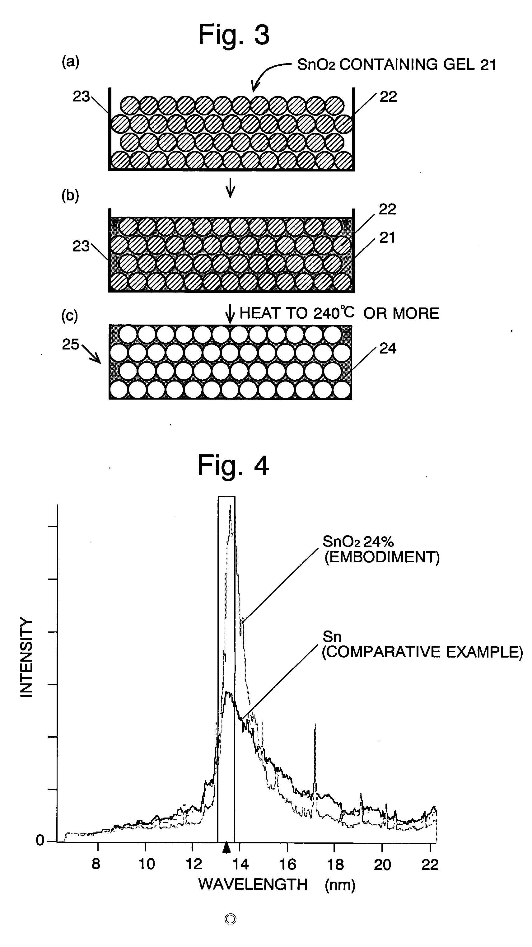
An object of the present invention is to provide an extreme ultravioletlight source target which can emits extreme ultraviolet light with high emission efficiency. A solid target made of heavy metal or heavy-metal compound and having a density 0.5 to 80% that of the crystal density is used. When the target is irradiated with a laser beam, plasma of the heavy metal contained in the target is generated, and extreme ultraviolet light having a predetermined wavelength which corresponds to the kind of the heavy metal is emitted from the plasma. When the density of the target is made to be smaller than the crystal density as described above, space distribution of the density of the generated plasma can be controlled, and the region in which plasma absorbs energy of the laser beam overlaps the region in which the plasma emits the extreme ultraviolet light. Thus, emission efficiency can be improved, preventing energy loss. For example, in a case where the SnO2 target having a density 24% of the crystal density is used, the emission efficiency at around 13.5 nm wavelength is higher than in the case where a Sn crystal target is used.
Description
TECHNICAL FIELD [0001] The present invention relates to a target for generating extreme ultraviolet light having a wavelength of 1 to 100 nm, to a manufacturing method of the target, and to an extreme ultravioletlight source using the target. The target and the extreme ultraviolet light source can be used suitably in a lithographic process for manufacturing semiconductor devices. BACKGROUND ART [0002] Semiconductor integrated circuits are generally manufactured using a lithographic process. Since the minimum processing dimension of lithography depends on the wavelength of light used, it is necessary to shorten the wavelength of the irradiated light in order to improve the integration degree of the integrated circuit. Specifically, the lithographic process is, at present, performed using light having a wavelength of 157 to 365 μm. An object is to achieve the practical use of the lithography using extreme ultraviolet light having a wavelength of 11 to 14 nm. [0003] For the light sour...
Claims
Application Information
Patent Timeline
Application Date:The date an application was filed.
Publication Date:The date a patent or application was officially published.
First Publication Date:The earliest publication date of a patent with the same application number.
Issue Date:Publication date of the patent grant document.
PCT Entry Date:The Entry date of PCT National Phase.
Estimated Expiry Date:The statutory expiry date of a patent right according to the Patent Law, and it is the longest term of protection that the patent right can achieve without the termination of the patent right due to other reasons(Term extension factor has been taken into account ).
Invalid Date:Actual expiry date is based on effective date or publication date of legal transaction data of invalid patent.
Patent Type & AuthorityApplications(United States)

