Methods to control water flow and distribution in direct methanol fuel cells

a technology of direct methanol and fuel cells, which is applied in the direction of fuel cells, solid electrolyte fuel cells, fuel cells, etc., can solve the problems of reduced power generation, excessive concentration of methanol, and deterioration of mea, and achieve good fuel efficiency and cell performance.

Inactive Publication Date: 2006-06-22
EC POWER LLC +1
View PDF8 Cites 27 Cited by
  • Summary
  • Abstract
  • Description
  • Claims
  • Application Information

AI Technical Summary

Benefits of technology

[0007] The present invention is intended to overcome the above problems and achieves a DMFC system operated directly on concentrated methanol solution by proper control of water flow and distribution inside the fuel cell, without external recovery of cathode water. A key feature of the present invention is to confine abundant water inside a region between the anode flow path and cathode catalyst layer, even with circulating air through a cathode flow channel. This is realized, on one side, by using a cathode microporous layer (MPL) which is made highly hydrophobic so that the product water can be pushed back into the anode through a thin membrane. On the other side of the region, namely on the outside of the anode flow path, a water barrier is inserted, which contains a number of elongated holes or pores in a plate of metals, polymers, or ceramics. This barrier has a unique property that it allows liquid flux only in the direction from the fuel flo

Problems solved by technology

An Excessively high concentration leads to a generation of a large amount of the crossover methanol and hence reduction of the power generation.
Moreover, in an extreme case, the excessively concentrated methanol may deteriorate the MEA.
On the con

Method used


Image

  • Methods to control water flow and distribution in direct methanol fuel cells
  • Methods to control water flow and distribution in direct methanol fuel cells
  • Methods to control water flow and distribution in direct methanol fuel cells

Examples


first embodiment

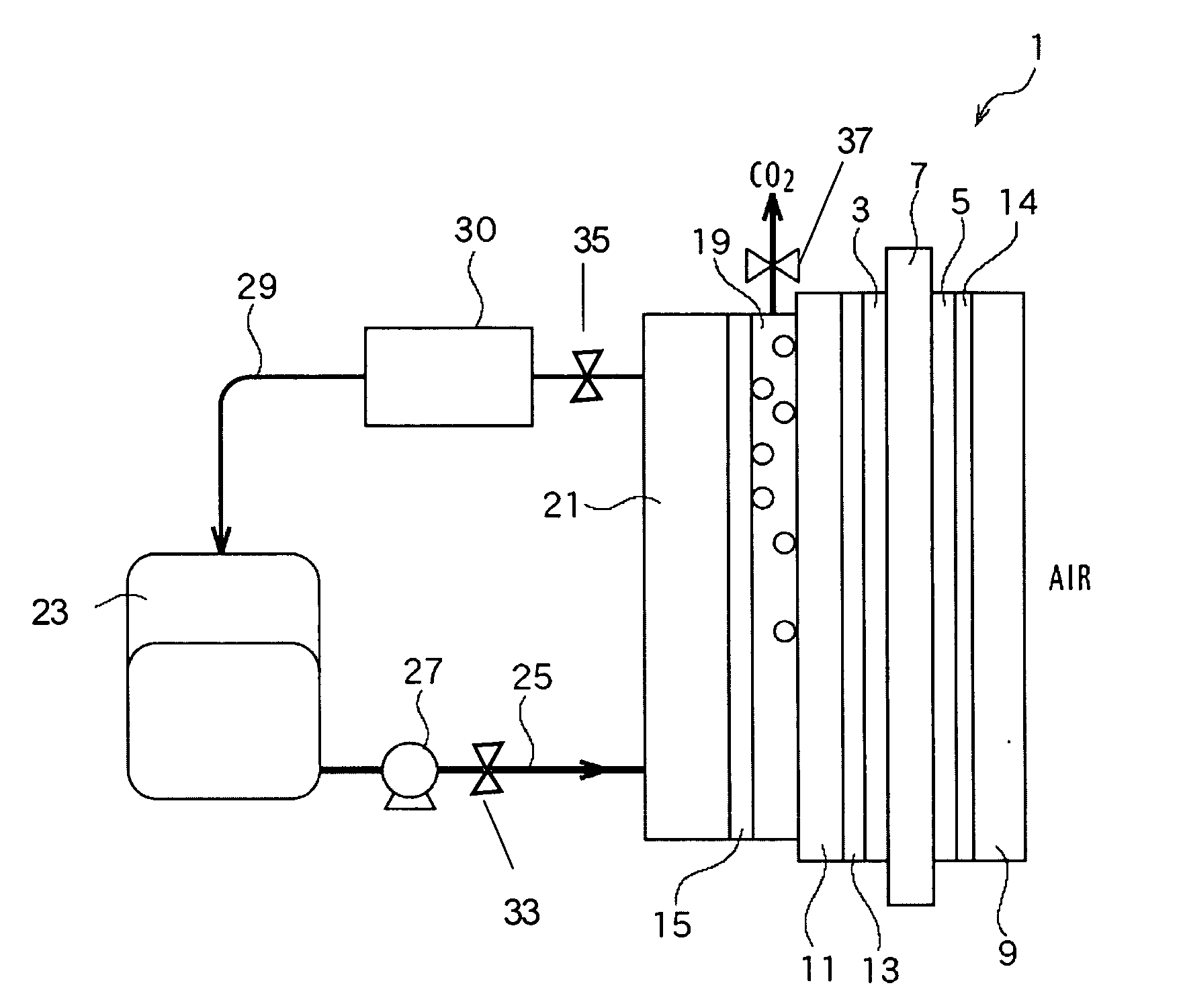
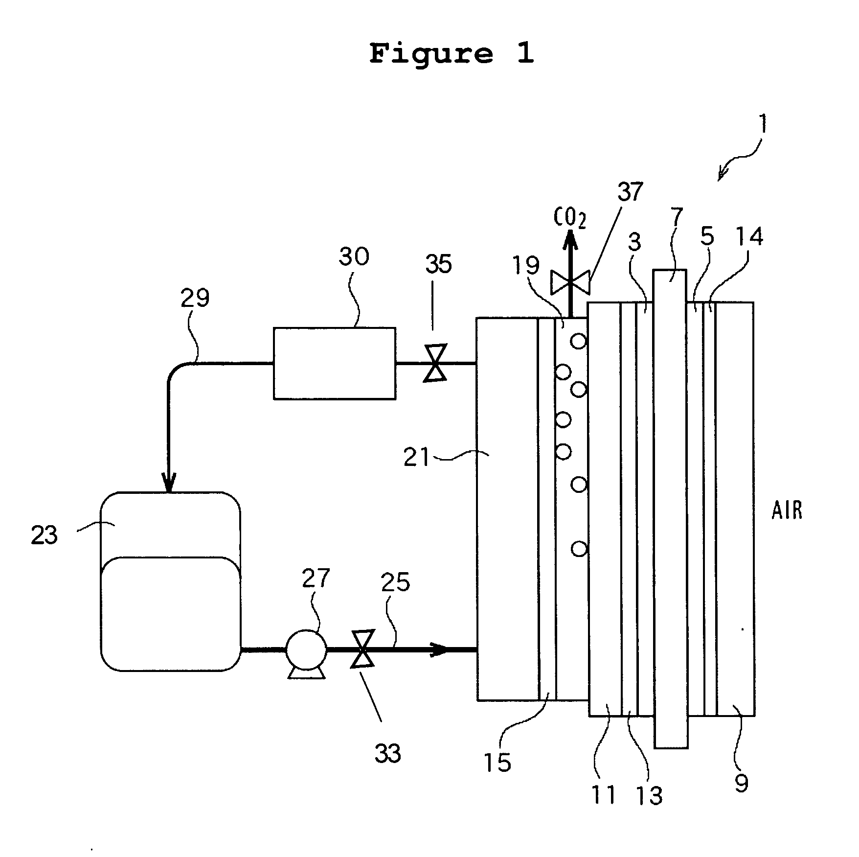
[0017] Referring to FIG. 1, a fuel cell system 1 according to the present invention is provided with a MEA having an anode catalyst layer 3, a cathode catalyst layer 5 and an electrolyte membrane 7 having proton conductivity put therebetween.

[0018] The anode catalyst layer 3 is for oxidizing a fuel (a methanol aqueous solution) and hence extracting electrons and protons therefrom. The anode catalyst layer 3 is provided with an anode gas diffusion layer 11 disposed adjacent thereto, made of carbon paper for example.

[0019] The cathode catalyst layer 5 is for oxygen reduction where electrons provided with a cathode gas diffusion layer 9 disposed adjacent thereto react with the protons generated at the anode catalyst layer 3 to form water at the cathode catalyst layer 5.

[0020] The electrolyte membrane 7 is made of any ion-exchange materials having proton conductivity. A preferable example thereof is a copolymer of tetrafluoroethylene and perfluorovinyl ether sulfonate and more prefera...

second embodiment

[0051] a porous body 35 is disposed between the fuel tank 23 and the assembly body 33 and the link flow path 25 and the fuel pump 27 are omitted.

[0052] Therefore the present embodiment takes substantially the same effects as the aforementioned first embodiment which allow the highly concentrated fuel to be housed in the fuel tank and the link flow path 25 and the fuel pump 27 can be omitted so that the whole constitution can be simplified.

third embodiment

[0053] the present invention will be described hereinafter with reference to FIG. 6. In the following description, substantially the same elements as any of the aforementioned embodiments are referenced with the same numerals and the detailed descriptions are omitted.

[0054] According to the present embodiment, a tank 41 stores a highly concentrated methanol and the concentrated methanol is supplied to the tank 23 by means of a pump P1. Furthermore, air is supplied to a cathode flow path 43 layered on an outer side of the cathode diffusion layer 9 and exhaust gas in the cathode flow path 43 is cooled at a condenser 45 so as to condense water vapor contained in the exhaust gas. The condensed water by means of the condenser 45 is recovered to the fuel tank 23 by means of a pump P3.

[0055] According to the present embodiment, provided that the concentration of the methanol aqueous solution stored in the fuel tank 23 varies in some degree, a variation of the concentration at the anode ca...


PUM


Abstract

A direct methanol fuel cell unit is provided with a fuel cell including an anode, a cathode with a hydrophobic microporous layer, an electrolyte membrane put in-between, and a fuel supply path supplying fuel to the anode. The fuel supply path is provided with an upwind water barrier preventing back-diffusion of water and a gas flow path channeling gas generated at the anode and disposed between the barrier and the anode. A water-rich zone is formed between the water barrier and the cathode microporous layer. Water loss from either side of this zone is eliminated or minimized, thereby permitting direct use of highly concentrated methanol in the fuel flow path with good fuel efficiency and power performance. The cell unit can be applied equally well to both an active circulating air cathode and an air-breathing cathode.

Description

FIELD OF THE INVENTION [0001] The present invention relates to a direct methanol fuel cell (DMFC) and a fuel cell system therewith, and, more particularly, to a DMFC operating on concentrated methanol at an anode thereof and a fuel cell system therewith. BACKGROUND OF THE INVENTION [0002] In general, a fuel cell is provided with a membrane electrode assembly (“MEA” hereinafter) having an anode, a cathode and an electrolyte membrane having proton conductivity put therebetween. In a case of a direct methanol fuel cell (“DMFC” hereinafter), methanol / water solution is supplied to the anode as a fuel and air is supplied to the cathode as an oxidant. The DMFC need not be provided with a reformer for extracting hydrogen from the fuel; thereby it is advantageous in view of downsizing thereof. [0003] The electrolyte membrane has a function of exchanging ions between the cathode and the anode and is necessary to be humidified with water. In general, the water for humidifying is either supplie...

Claims


Application Information

Patent Timeline
IPC IPC(8): H01M8/10
CPCH01M8/04186H01M8/04291H01M8/1011Y02E60/523Y02E60/50
Inventor WANG, CHAO-YANGLU, GUOQIANGLIU, WENPENGLIU, FUQIANGSATO, YUUSUKESAKAUE, EIICHIMATSUOKA, KEI
Owner EC POWER LLC
Why Eureka
Try Eureka