Image forming apparatus with heat control of image bearing member

a technology of image bearing and heat control, which is applied in the field of image forming apparatus, can solve the problems of power consumption, uneven density or some defects in the output image, and the quality of the formed image is reduced, so as to reduce the heat applied, and reduce the effect of moistur

Inactive Publication Date: 2006-06-29
CANON KK
View PDF7 Cites 10 Cited by
  • Summary
  • Abstract
  • Description
  • Claims
  • Application Information

AI Technical Summary

Benefits of technology

[0015] The present invention provides an image forming apparatus for efficiently eliminating moisture on the surface of a photosensitive drum by heating the surface in a short time with minimal power consumption. The present invention also provides an image forming apparatus that eliminates a problem caused by heat being applied to parts other than the photosensitive drum by reducing the heat applied to those parts.

Problems solved by technology

Accordingly, the electrostatic charge retention properties of the drum may deteriorate, thus decreasing the quality of a formed image.
Because a difference in the electrostatic charge retention function between the zones facing and not facing the corona chargers exists, uneven density or some defects may appear in the output image.
When a resistance heating heater is provided in a photosensitive drum and is always in the power-on mode, power is consumed even during power-off time of a copying machine or printer and even out of hours.
This power consumption does not meet the increasing demand for power and energy conservation.
In the case of the preheating method discussed in Japanese Examined Utility Model Registration Application Publication No. 1-34205, the heat is dissipated together with the heated air, and therefore, heating efficiency is low.
In addition, the temperature of the surface of the photosensitive drum does not rise rapidly, and therefore, a lengthy warm-up time is required for starting up the apparatus and starting up the printing process.
However, since the heat is transferred by an air layer, the heating efficiency is low.
Thus, the temperature of the surface of the photosensitive drum rises slowly despite high power consumption of the heating element.
If the power consumption of the heating element is increased to speed up the temperature rise, electric elements and components around the heating element are unnecessarily heated, and therefore, an additional cooling fan is required to cool an electronic circuit in the image forming apparatus.

Method used


Image

  • Image forming apparatus with heat control of image bearing member
  • Image forming apparatus with heat control of image bearing member
  • Image forming apparatus with heat control of image bearing member

Examples


first exemplary embodiment

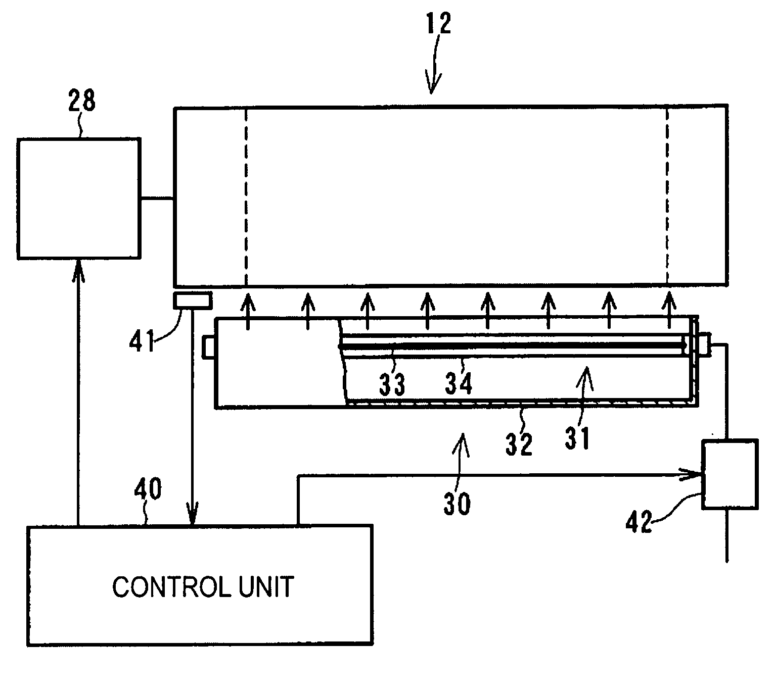
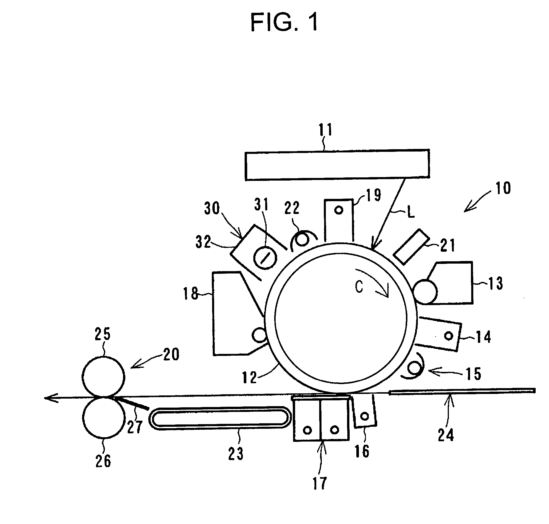
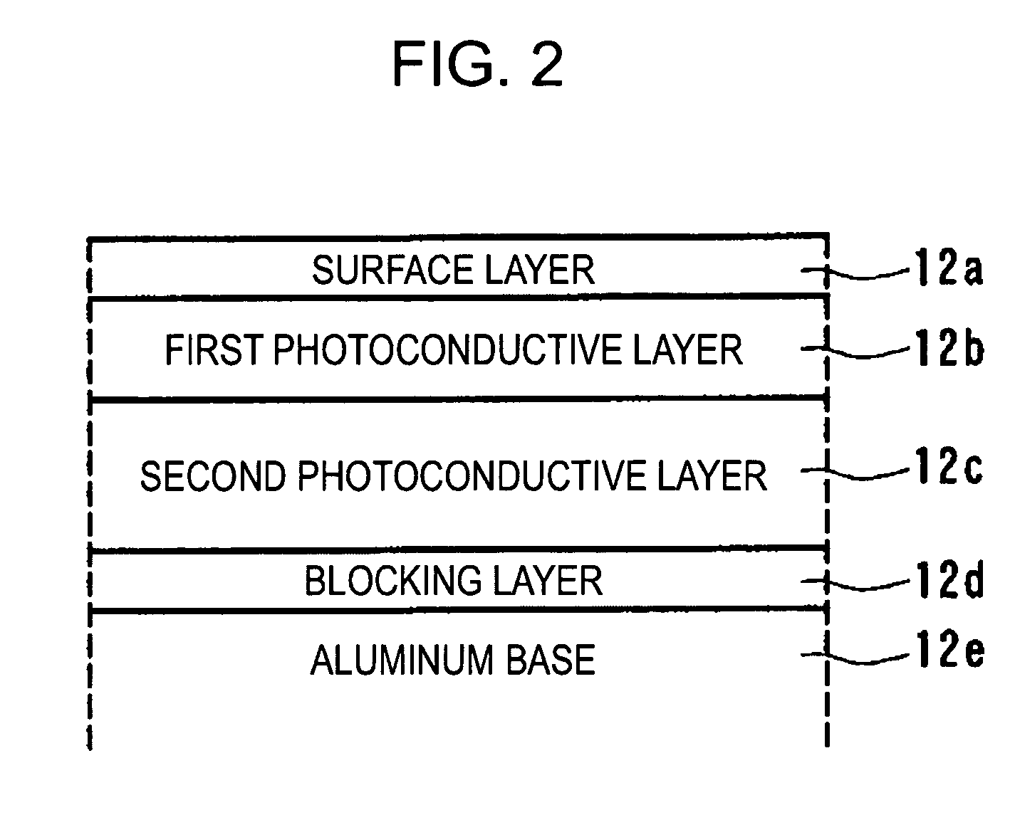
[0035]FIG. 1 is a block diagram of an image forming apparatus according to a first exemplary embodiment of the present invention. FIG. 2 illustrates the surface structure of a photosensitive drum. FIG. 3 is a diagram illustrating the heating control process of the photosensitive drum. FIG. 4 is a diagram illustrating the radiation spectrum of a carbon lamp heater. FIG. 5 illustrates the distribution of the anisotropic radiation intensity of the carbon lamp heater. FIG. 6 is a flow chart of the heating control process.

[0036] According to this embodiment, as shown in FIG. 1, an image forming apparatus 10 (an electrophotographic monochrome laser beam printing apparatus) includes a photosensitive drum 12 (image bearing member) adjacent to a transport path of a sheet of material (transfer material) 24. The image forming apparatus 10 further includes a discharge exposure lamp 22, a primary charger 19, an exposure unit 11, an electric potential sensor 21, a developer unit 13, a pre-transf...

second exemplary embodiment

[0088]FIG. 7 illustrates the result of experiments by an image forming apparatus according to a second exemplary embodiment of the present invention.

[0089] To determine the effect of the carbon lamp heater 31 shown in FIG. 5, a series of experiments was conducted by the present inventor to determine whether image deletion occurs or not depending on various structures of a heating unit.

[0090] A copying machine (iR8500 available from CANON KABUSHIKI KAISHA) was modified, as shown in FIG. 1. After the surface temperature of the photosensitive drum 12 was adjusted to 40° C. using the carbon lamp heater 31 having the distribution of anisotropic radiation intensity, images were continuously formed on 5000 sheets of material. Subsequently, the main body and the carbon lamp heater 31 were powered off and were left unused overnight in a high-temperature and high-humidity environment with a temperature of 30° C. and a relative humidity of 80%. On the following day, the carbon lamp heater 31...

third exemplary embodiment

[0097]FIG. 8 illustrates the control of lamp heater heating means in an image forming apparatus according to a third exemplary embodiment of the present invention.

[0098] According to the third embodiment, the structure of an image forming apparatus is similar to that of the image forming apparatus of the first embodiment shown in FIGS. 1 through 5. In this embodiment, the speed control of the photosensitive drum 12 shown in FIG. 6 and the output control of a carbon lamp heater shown in FIG. 8 are added to this structure.

[0099] That is, the control unit 40 shown in FIG. 3 performs on and off control of switch 42 to apply a pulse current to the carbon lamp heater 31 and changes the width of the pulse so as to continuously adjust the output of the carbon lamp heater 31.

[0100] As shown in FIG. 8, at step 121, the control unit 40 determines whether the image forming apparatus 10 is performing a printing operation. If the image forming apparatus 10 is performing a printing operation, t...


PUM


Abstract

An image forming apparatus has an image bearing member on which an electrostatic latent image is formed and toner deposited to form a toner image, a heater disposed at a position out of contact with the surface of the image bearing member to output radiant heat to the image bearing member, and a heat controller for controlling rotation of the image bearing member and heat output by the heater to heat the outer peripheral surface of the image bearing member moving relative to the heater. The heater includes a lamp heater having a radiation spectrum that exhibits a major part of the peak intensity in the range of infrared wavelength from 2 to 3.5 μm.

Description

BACKGROUND OF THE INVENTION [0001] 1. Field of the Invention [0002] The present invention relates to an image forming apparatus, such as a copying machine, a printer, or a facsimile, that forms an image by means of electrophotography. [0003] 2. Description of the Related Art [0004] An image forming apparatus that forms an image by means of electrophotography includes a photosensitive drum serving as an image bearing member and a plurality of corona chargers arranged around the photosensitive drum. The plurality of corona chargers include a primary charger, a pre-transfer charger, a transfer charger, and a detach charger. [0005] When activated, these corona chargers generate active substances (e.g., ozone and oxides of nitrogen). Some of these active substances change the chemical composition and the crystalline structure of the surface of the photosensitive drum. The change in the chemical composition and the crystalline structure of the surface may increase the hygroscopic property...

Claims


Application Information

Patent Timeline
Patent Type & Authority Applications(United States)
IPC IPC(8): G03G15/00
CPCG03G15/2007G03G15/5045G03G15/5008
Inventor MATSUURA, DAIGO
Owner CANON KK
Why Eureka
Try Eureka