Wireless sensor, rolling bearing with sensor, management apparatus and monitoring system

a technology of sensor and rolling bearing, which is applied in the direction of electric signalling details, instruments, mechanical equipment, etc., can solve the problems of difficult to detect abnormalities, difficult to compact the unit, and produce vibration (that is, a change of acceleration) , to achieve the effect of high accuracy

Inactive Publication Date: 2006-07-06
NSK LTD
View PDF12 Cites 67 Cited by
  • Summary
  • Abstract
  • Description
  • Claims
  • Application Information

AI Technical Summary

Benefits of technology

[0020] It is a second object of the invention to provide a bearing unit and a linear motion unit in which signals of rotation speed, temperature, vibration (acceleration) and so on can be transmitted to a control unit attached to the vehicle body side in the condition that there is negligible distortion in the output waveform or negligible influence of noise.
[0021] It is a third object of the invention to provide a bearing unit with sensor with a compact sensor in which the vibration condition of bearings can be detected with high accuracy.
[0022] It is a fourth object of the invention to provide a low-price and compact bearing unit with sensor and a low-price and compact linear motion unit with sensor in which the condition of vibration ranging from a low frequency to a high frequency can be detected.

Problems solved by technology

Bearings for supporting rotating shafts as axles of vehicle such as cars and railway vehicles, or linear motion units such as ball screws or linear guides and bearings applied to industrial machines such as processing machines or assembling machines may produce vibration (that is, a change of acceleration) due to motion or heat due to friction.
Further, when abnormality is slight, it is difficult to detect the abnormality in an early stage of the abnormality occurrence in which the bearing temperature does not increase so much.
As a result, it is difficult to make the unit compact.
However, since the distance between the sensors 1104 and 1106 attached to the bearing unit and the control unit attached to the vehicle body side is 10-20 m, the signals of the rotation speed, the temperature and so on detected by the sensors 1104 and 1106 are easily distorted in their output waveforms or affected by noise due to the signal transmission.
Particularly, the analog temperature signal is easily distorted in its output waveform or affected by noise, so as to cause the deterioration of measuring accuracy.
In addition, when the temperature signal which is an analog signal is transmitted through a cable together with the rotation speed signal which is a digital signal, noise from the rotation speed signal may be superimposed on the analog temperature signal due to electromagnetic coupling (coupling based on electrostatic coupling, electromagnetic induction or electromagnetic waves).
As a result, the wiring processing of the cables 2108 and 2110 becomes troublesome while the number of parts for the wiring processing increases so that the manufacturing cost of the unit increases.
However, since initial symptoms of abnormal vibration such as infinitesimal deformation, microcrack, abrasion, flaking or peeling appear before the deformation or failure of the member, and the vibration at this time has a form of infinitesimal elastic waves (high frequency vibration) with a high-frequency component of 10 kHz or higher, the vibration condition cannot be detected sensitively.
As a result, even if abnormality begins to appear in the rolling bearing 2100, the symptoms of the abnormality cannot be detected in an early stage.
Thus, it is difficult to plan preventive maintenance for the unit.
It is therefore difficult for the vibration sensor 2100 described above to detect the vibration waves accurately.
As a result, it is impossible to grasp the abnormality of the bearing in an early stage.
Thus, it is impossible to grasp the symptoms of abnormality such as seizure in an early stage.

Method used


Image

  • Wireless sensor, rolling bearing with sensor, management apparatus and monitoring system
  • Wireless sensor, rolling bearing with sensor, management apparatus and monitoring system
  • Wireless sensor, rolling bearing with sensor, management apparatus and monitoring system

Examples


first embodiment

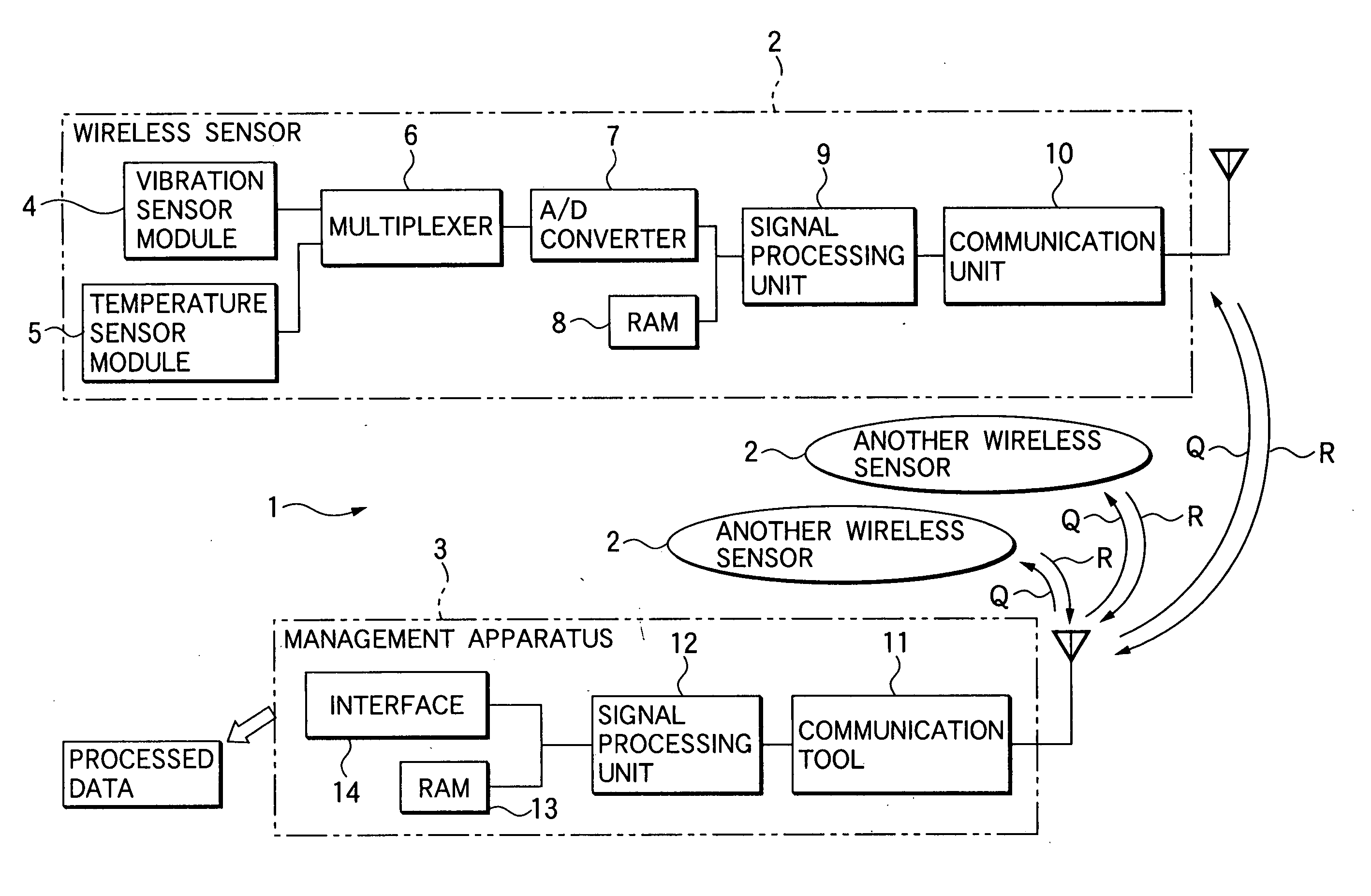
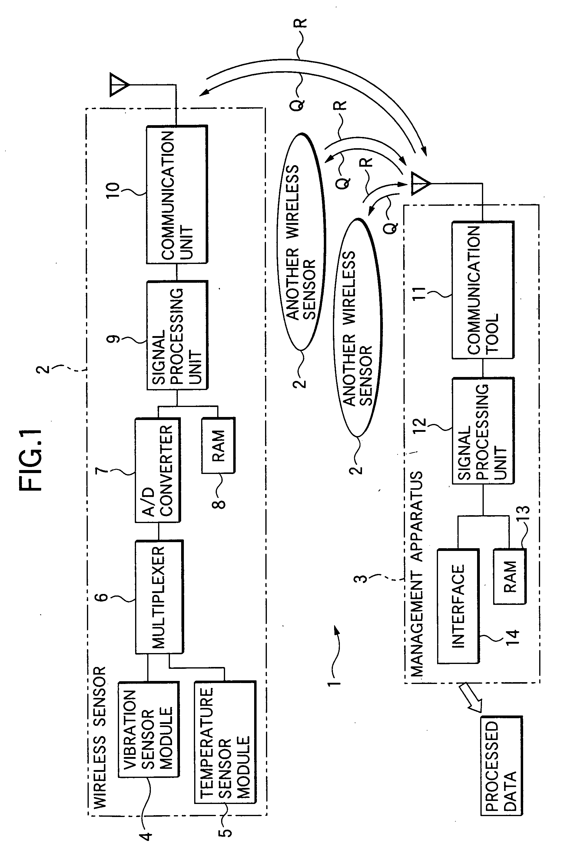
[0127] the invention will be described with reference to FIGS. 1 to 3. A monitoring system 1 shown in FIG. 1 is constituted by a plurality of wireless sensors 2 and management apparatus 3. Each of the wireless sensors 2 detects vibration or temperature as a subject of detection and transmits the detection data (signal) thereof. The management apparatus 3 receives signals R output from the plurality of wireless sensors 2.

[0128] Each wireless sensor 2 has a vibration sensor module 4, a temperature sensor module 5, a multiplexer 6, an A / D converter 7, a RAM (Random Access Memory) 8, a signal processing unit 9 and a communication unit 10. The vibration sensor module 4 has a vibration sensor as a detection unit for detecting vibration as a subject of detection, so as to convert the change of vibration detected in the form of acceleration or the like into an electric signal, and output the electric signal. The temperature module 5 has a temperature sensor as a detection unit for detecting...

second embodiment

[0154] Next, the invention will be described with reference to FIGS. 4A to 5. A rolling bearing unit 31 shown in FIG. 4A has a bearing unit 32 and a sensor unit 33 which is a wireless sensor. The bearing unit 32 has inner and outer rings 34 and 35, rolling elements 36 disposed between these raceway rings 34 and 35, a retainer 37 for the rolling elements 36, and a seal or shield plate 351. The sensor unit 33 has a detection unit 38, a processing unit 39, a communication unit 40, and cells (batteries) 41 as shown in FIG. 4B. The detection unit 38 detects a subject of detection. The processing unit 39 processes detected data. The communication unit 40 transmits a signal output from the processing unit 39 by wireless. The cells 41 supply electric power to the detection unit 38, the processing unit 39 and the communication unit 40.

[0155] The sensor unit 33 is attached to a flange 43 formed toward the center of an outer ring spacer 42 integrally fixed or closely contacted to the outer rin...

third embodiment

[0183] Incidentally, the speed sensor module 79 may have a coil 83 and a rod-like pole 84 disposed in the center of the coil 83, or may be an annular coil twisted circumferentially at each convex portion 78 of the pulsar ring 68. The pulsar ring 68 and the speed sensor module 79 may be disposed among the rolling elements 73. In addition, the form of the speed sensor module may be either a passive type illustratively applied to the hub bearing unit in the third embodiment, or an active type. When an active type speed sensor module is used, a power generating coil is provided separately.

[0184] Although a ball bearing using balls as rolling elements is used for the hub bearing unit 64 shown in FIG. 7, a cylindrical roller bearing or a tapered roller bearing may be used. Alternatively, single row bearings may be used in combination. In addition, the vibration sensor module 4 and the temperature sensor module 5 shown in the first embodiment, and the vibration sensor 44 and the temperatur...


PUM


Abstract

The wireless sensor adds identification information peculiar to respective sensor modules to detection data of vibration, temperature, and soon, detected by the sensor modules respectively. The wireless sensor transmits the detection data with the identification information as a signal through a communication unit by radio waves. On the other hand, the management apparatus receiving the signal classifies and files the detection data on the basis of the identification information included in the signal. Then, the monitoring system is designed to make the management apparatus manage a plurality of wireless sensors attached to movable shafts of processing machines or the like.

Description

BACKGROUND OF THE INVENTION [0001] 1. Field of the Invention [0002] The present invention relates to a bearing unit with sensor which detects the condition (including vibration, temperature, rotation speed and the like) of a bearing, a gear box, a spindle or the like incorporated in machinery (for example, a movable body such as a railway vehicle, a car or a guided vehicle, or a mechanical equipment such as a continuous-casting machine or a rolling mill), so that preventive maintenance can be achieved thereon. [0003] In addition, the invention relates to a linear motion unit with sensor which detects the condition (including vibration, temperature, speed and the like) of a ball screw, a linear guide or the like incorporated in a lathe, a machining center, an injection molder, semiconductor manufacturing equipment or the like, so that preventive maintenance can be achieved thereon. [0004] In addition, the invention relates to a wireless sensor attached to an industrial machine or a v...

Claims


Application Information

Patent Timeline
Patent Type & Authority Applications(United States)
IPC IPC(8): G08B21/00G08B1/08F16C19/52G01H1/00G01P3/44G01V1/22
CPCF16C19/525G01H1/003G01M13/045G01P3/443G01V1/223F16C41/008
Inventor SAKATANI, IKUNORIMORITA, KOUICHITAKIZAWA, TAKESHIENDO, SHIGERUYANAGISAWA, TOMOYUKISHODA, YOSHIO
Owner NSK LTD
Why Eureka
Try Eureka