Micro corner cube array, method of making the micro corner cube array and reflective type display device
- Summary
- Abstract
- Description
- Claims
- Application Information
AI Technical Summary
Benefits of technology
Problems solved by technology
Method used
Image
Examples
embodiment 1
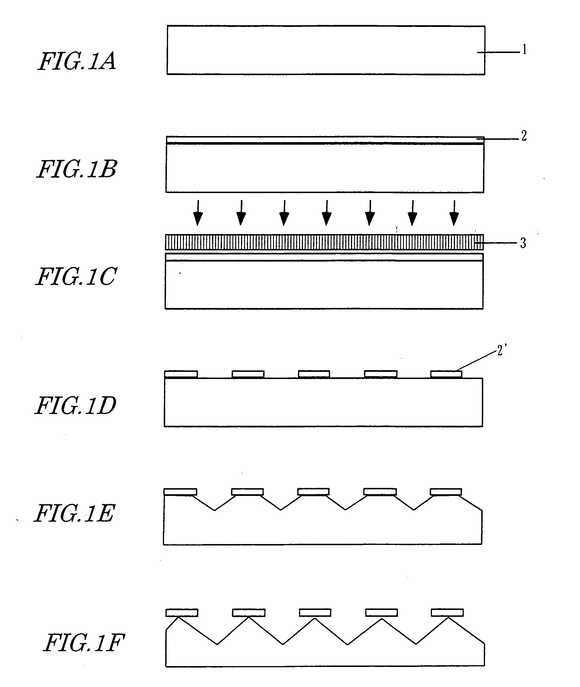
[0152]FIGS. 1A through 1F illustrate respective process steps for making a micro corner cube array according to a first specific preferred embodiment of the present invention. In this preferred embodiment, a single crystalline substrate of GaAs, which is an exemplary compound semiconductor having a sphalerite structure, is used as the cubic single crystalline substrate on which a micro corner cube array should be formed.
[0153] First, as shown in FIG. 1A, a substrate 1, which consists of GaAs single crystals and of which the surface is one of {111}B planes, is prepared and has that surface mirror-polished. It should be noted that {111}A planes are formed by gallium atoms, while the {111}B planes are formed by arsenic atoms. FIG. 41 shows one of the {111}B planes of GaAs single crystals as viewed from over the substrate 1. In FIG. 41, the configuration of the GaAs crystal unit cell is indicated by the one-dot chains.
[0154] Next, as shown in FIG. 1B, the surface of the substrate 1 is...
embodiment 2
[0166]FIGS. 5A through 5I illustrate respective process steps for making a micro corner cube array according to a second specific preferred embodiment of the present invention. In this preferred embodiment, a substrate consisting of germanium single crystals having a diamond structure is used as the cubic single crystalline substrate on which a micro corner cube array should be formed.
[0167] First, in the process step shown in FIG. 5A, a substrate 4, which consists of germanium single crystals and of which the surface is parallel to a (111) plane of the germanium crystals, is prepared and has that surface mirror-polished. Next, an SiO2 layer 5 is deposited by a CVD process, for example, to a thickness of about 200 nm on the mirror-polished surface of the substrate 4. Then, the surface of the SiO2 layer 5 is spin-coated with a positive photoresist layer 2 with a thickness of about 1 μm. The photoresist layer 2 may be made of OFPR-800 (produced by Tokyo Ohka Kogyo Co., Ltd.), for exa...
embodiment 3
[0180] Hereinafter, a method of making a micro corner cube array according to a third specific preferred embodiment of the present invention will be described. In this third preferred embodiment, a micro corner cube array is also formed on the surface of a single crystalline substrate by subjecting the substrate to an anisotropic etching process as in the first and second preferred embodiments described above. However, in this preferred embodiment, multiple different types of solutions are used as etchants for the anisotropic etching process.
[0181] As shown in FIG. 19A, a GaAs substrate 101 is used as the single crystalline substrate and is selectively covered with an etching mask (i.e., the masking elements of the etching mask layer) 102. Then, the substrate 101 is etched anisotropically though the mask 102, thereby making a micro corner cube array.
[0182] In this preferred embodiment, to investigate exactly how the shape of the resultant micro corner cube array changes with the t...
PUM
| Property | Measurement | Unit |
|---|---|---|
| Length | aaaaa | aaaaa |
| Length | aaaaa | aaaaa |
| Size | aaaaa | aaaaa |
Abstract
Description
Claims
Application Information
 - R&D
- Intellectual Property
- Life Sciences
- Materials
- Tech Scout
- Unparalleled Data Quality
- Higher Quality Content
- 60% Fewer Hallucinations
Browse by: Latest US Patents, China's latest patents, Technical Efficacy Thesaurus, Application Domain, Technology Topic, Popular Technical Reports.
© 2025 PatSnap. All rights reserved.Legal|Privacy policy|Modern Slavery Act Transparency Statement|Sitemap|About US| Contact US: help@patsnap.com


