
Video coding

a video and coding technology, applied in the field of data transmission, can solve the problems of inability to achieve a sufficient level of compression, the gateway may occasionally have to discard datagrams, and the video encoders also try to reduce the quality of those parts of the video sequen

Inactive Publication Date: 2006-07-06
CORE WIRELESS LICENSING R L
View PDF2 Cites 102 Cited by
  • Summary
  • Abstract
  • Description
  • Claims
  • Application Information

AI Technical Summary

Benefits of technology

[0128] The invention enables an improvement in the coding efficiency when shortening a temporal prediction path. It further has the effect of increasing the resilience of an encoded video signal to degradations resulting from loss or corruption of data in a bit-stream carrying information for the reconstruction of the video signal.
[0209] In another error concealment approach, the encoder can provide the decoder with an indication of how to construct a virtual spare reference picture that can be used as a reference frame for motion compensated prediction if the actual reference picture is lost or becomes too corrupted to be used.

Problems solved by technology

Since no resources are permanently committed within the gateways to any particular connection, the gateways may occasionally have to discard datagrams because of lack of buffer space or other resources.
Thus, the delivery service offered by IP is a best effort service rather than a guaranteed service.
A sufficient level of compression cannot usually be reached just by reducing the redundancy of a video sequence.
Therefore, video encoders also try to reduce the quality of those parts of the video sequence which are subjectively less important.
INTER frames employing motion-compensation are rarely precise enough to allow sufficiently accurate image reconstruction and so a spatially compressed prediction error image is also associated with each INTER frame.
Additionally, bit-rate scalability means that the processing power needed for decoding a lower quality representation of the video sequence is lower than when decoding the full quality sequence.
One problem with scalable multi-media coding is that it often suffers from a worse compression efficiency than non-scalable coding.
However, the improvement in compression performance provided by B-frames is achieved at the expense of increased computational complexity and memory requirements.
In some cases, when reference layer pictures are poorly predicted, over-coding of static parts of the picture can occur in the enhancement layer, requiring an excessive bit rate.
One problem with conventional SNR scalability coding is termed drifting.
In addition, since the enhancement layers are based on the base layer, an error in the base layer causes errors in the enhancement layers.
Because prediction also occurs between the enhancement layers, a serious drifting problem can occur in the higher layers of subsequent predicted frames.
Even though there may subsequently be sufficient bandwidth to send data to correct an error, the decoder is not able to eliminate the error until the prediction chain is re-initialised by another INTRA picture representing the start of a new GOP.
However, since prediction is always based on a low quality base-layer, the coding efficiency of FGS coding is not as good as, and is sometimes much worse than, conventional SNR scalability schemes such as, those provided for in H.263 Annex O.
However, predictive coding is vulnerable to transmission errors, since an error affects all pictures that appear in a chain of predicted pictures following that containing the error.
However, it should be noted that conventional spatial and QSNR scalability coding, as well as FGS coding, decrease compression efficiency.
However, if the time between consecutive anchor frames is relatively long, the use of B-frames causes a reduction in compression efficiency.
This yields a worse predicted B-frame and consequently more bits are required to code the associated prediction error frame.
However, although reference picture selection can be used to reduce the temporal propagation of errors in a video sequence, it also has the effect of decreasing compression efficiency.
This leads to a substantial coding penalty because of the generally larger differences between consecutive pictures in the same thread and the longer motion vectors typically required to represent motion-related changes between pictures within a thread. FIG. 12 shows VRC operating with two threads and three frames per thread.
If the threads are reasonably short however, both forms of degradation only persist for a very short time, that is until the next Sync frame is reached.
However, as has been discussed in the foregoing, errors adversely affect efficiently coded data and so some awareness of possible errors is included.
Typically this is insufficient to carry a whole picture, and therefore the VCL is likely to divide a picture into multiple partitions so that each partition fits into one service data unit.
If a bit error affects an H.223 service data unit carrying video data, the decoder may lose decoding synchronisation due to variable length coding of the parameters, and it will not be possible to decode the rest of the data in the service data unit.
IP network elements, such as routers, may become congested due to excessive IP traffic, causing internal buffer overflows.
The packetisation overhead becomes significant in low-bit rate links if small packets are used.

Method used


Image

  • Video coding
  • Video coding
  • Video coding

Examples


Embodiment Construction

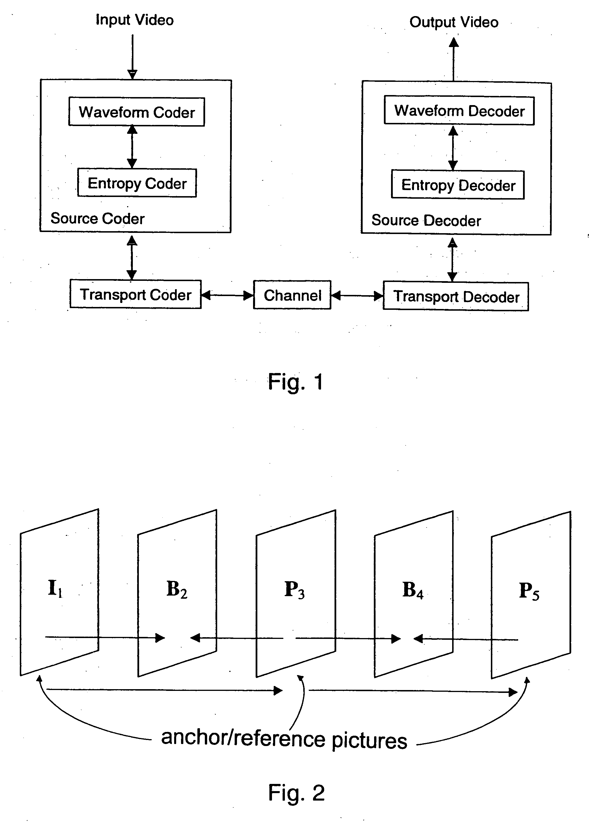
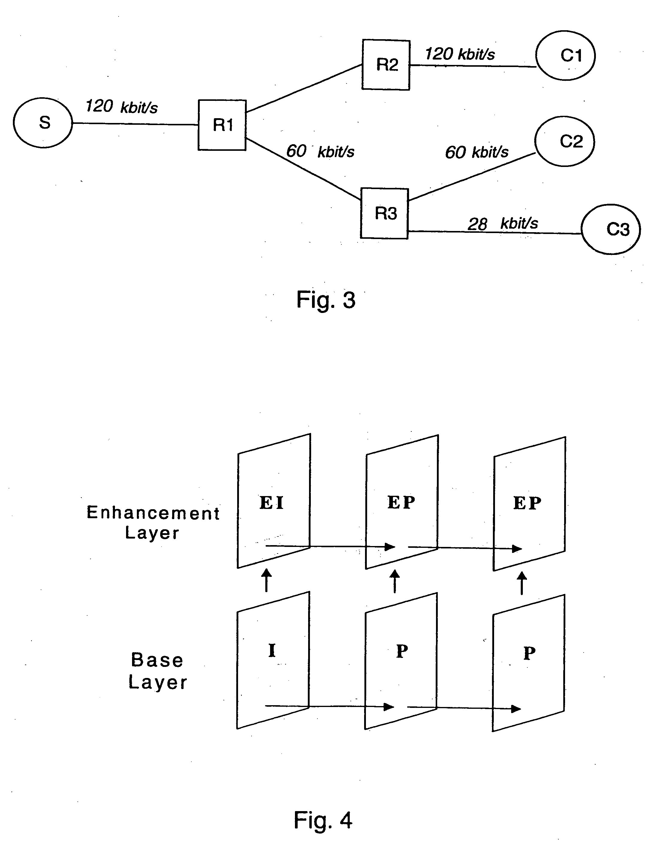
[0236] FIGS. 1 to 17 have been described in the foregoing.

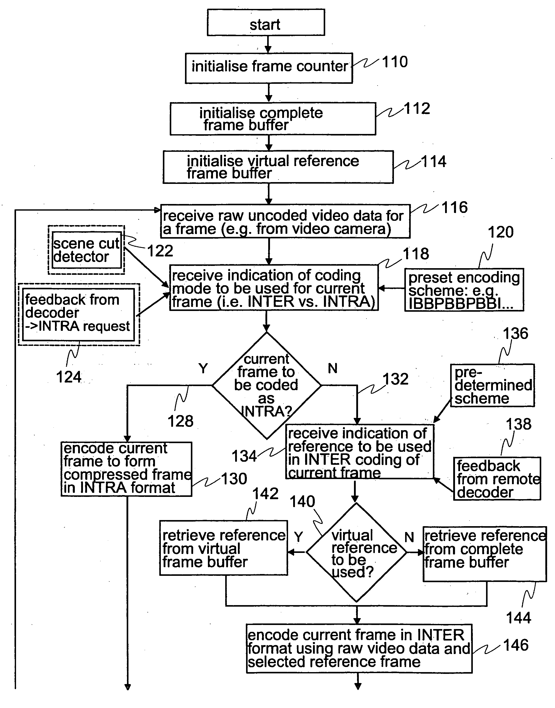
[0237] The invention will now be described in greater detail as a set of procedural steps with reference to FIG. 18, which illustrates an encoding procedure carried out by an encoder and to FIG. 19, which illustrates a decoding procedure carried out by a decoder corresponding to the encoder. The procedural steps presented in FIGS. 18 and 19 may be implemented in a video transmission system according to FIG. 16.

[0238] Reference will first be made to the encoding procedure illustrated by FIG. 18. In an initialization phase, the encoder initialises a frame counter (step 110), initialises a complete reference frame buffer (step 112) and initialises a virtual reference frame buffer (step 114). The encoder then receives raw, that is uncoded, video data from a source (step 116), such as a video camera. The video data may originate from a live feed. The encoder receives an indication of the coding mode to be used in the coding of a...


PUM


Abstract

A method for encoding a video signal comprises the steps of: encoding a first complete frame by forming a bit-stream containing information for its subsequent full reconstruction (150) the information being prioritised (148) into high and low priority information; defining (160) at least one virtual frame on the basis of a version of the first complete frame constructed using the high priority information of the first complete frame in the absence of at least some of the low priority information of the first complete frame; and encoding (146) a second complete frame by forming a bit-stream containing information for its subsequent full reconstruction the information being prioritised into high and low priority information enabling the second complete frame to be fully reconstructed on the basis of the virtual frame rather than on the basis of the first complete frame. A corresponding decoding method is also described.

Description

FIELD OF THE INVENTION [0001] The invention relates to data transmission and is particularly, but not exclusively, related to transmission of data representative of picture sequences, such as video. It is particularly suited to transmission over links susceptible to errors and loss of data, such as over the air interface of a cellular telecommunications system. BACKGROUND OF THE INVENTION [0002] During the past few years, the amount of multi-media content available through the Internet has increased considerably. Since data delivery rates to mobile terminals are becoming high enough to enable such terminals to retrieve multi-media content, it is becoming desirable to provide such retrieval from the Internet. An example of a high-speed data delivery system is the General Packet Radio Service (GPRS) of the planned GSM phase 2+. [0003] The term multi-media as used herein includes both sound and pictures, sound only and pictures only. Sound includes speech and music. [0004] In the Inter...

Claims


Application Information

Patent Timeline
IPC IPC(8): H04N7/12H04N11/04H04B1/66H04N11/02H03M7/36H04N7/24H04N7/26H04N19/37
CPCH04N21/23406H04N21/234327H04N21/44004H04N21/631H04N21/6379H04N19/00569H04N21/6583H04N19/50H04N19/37H04N19/34H04N19/36H04N21/64322
Inventor CAGLAR, KEREMHANNUKSELA, MISKA
Owner CORE WIRELESS LICENSING R L
Learn More