Catheterscope 3D guidance and interface system

a technology of bronchoscopy and interface system, which is applied in the field of bronchoscopy 3d guidance and interface system, can solve the problems of difficult to reach in order to take tissue samples, difficult diagnostic problems, and current bronchoscopy only being able to fit within the relative large branches

Active Publication Date: 2006-07-06
UNIV OF WASHINGTON
View PDF32 Cites 408 Cited by
  • Summary
  • Abstract
  • Description
  • Claims
  • Application Information

AI Technical Summary

Benefits of technology

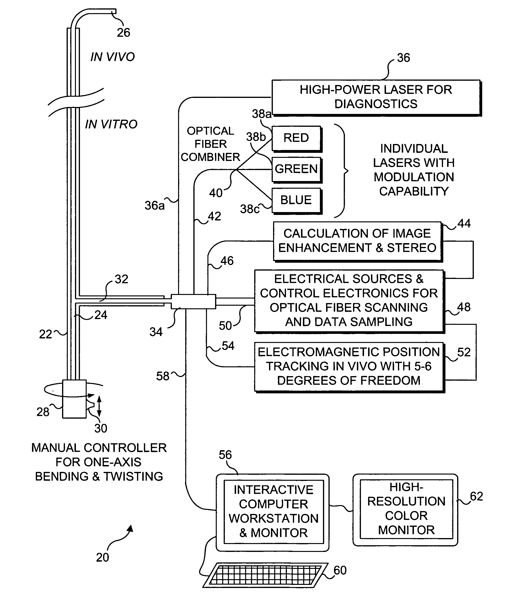
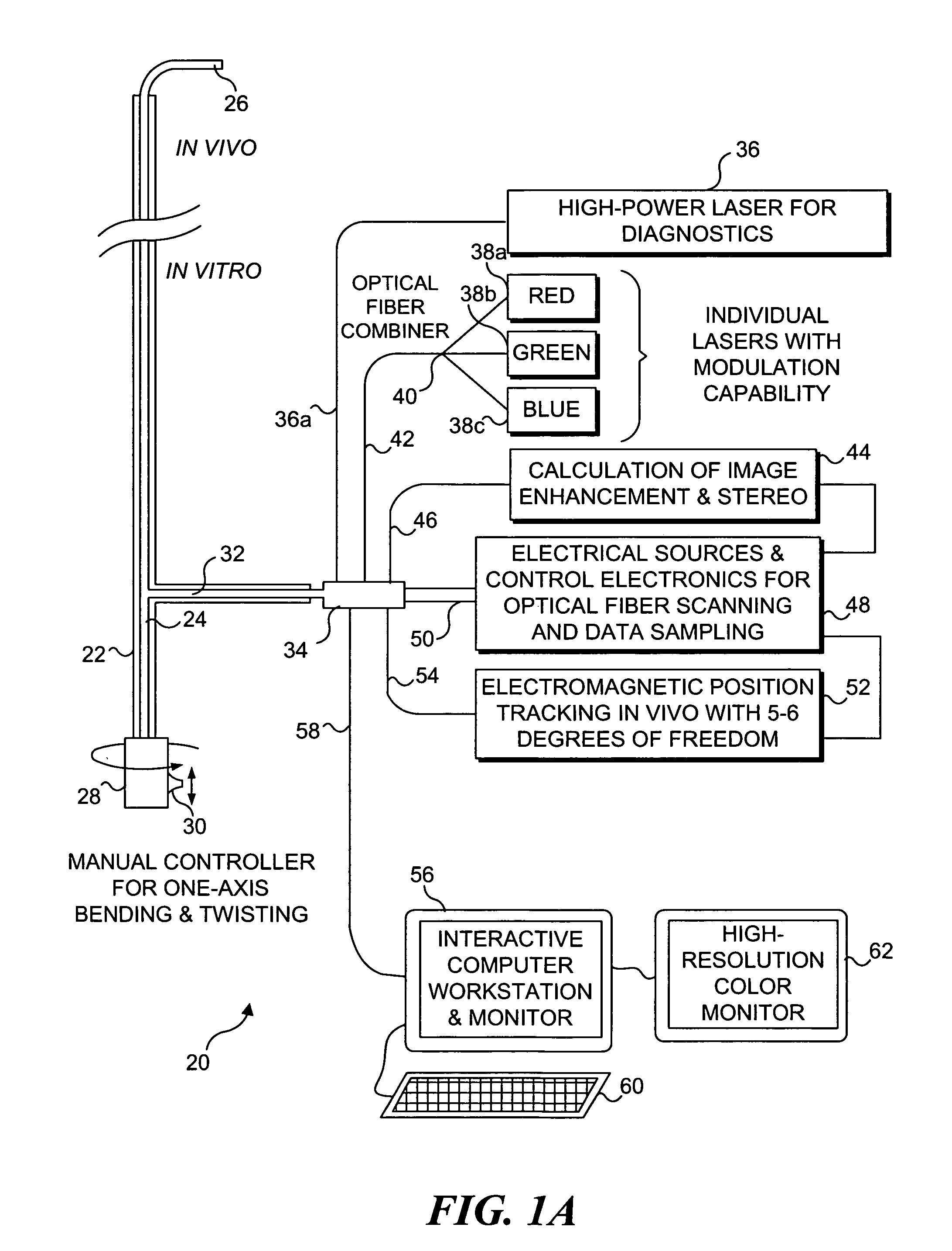
[0010] In addition to the surface model, an airway tree model is constructed to outline the hierarchy and connectivity of bifurcations originating at the main carina and extending down the bronchial tree. Within this airway tree model, branch points are represented by their 3-D position, a generation index that specifies how many levels separate the node from the main carina, the branching angles of the two subtending vessels, and a definition of the centerlines that connect two linked branch points. Based on the known position of potentially cancerous lesions on a HRCT scan, a number of nearby biopsy points are selected for inspection. From these points, a series of courses are automatically plotted in the model tree to effectively steer the physician at each branching while recording and graphically indicating regions previously inspected during the procedure to prevent over-sampling of the same region as well as ensuring a comprehensive probing of potentially affected areas.
[0011] The identification of bifurcations by the clinician on video images serves to confirm that the measured real-time position of the scope head aligns with its inferred position on the visual 3-D model and continually recalibrates the two to reduce accumulating errors. Recalibration involves a point to point re-registration of the lung model bifurcation location to the known position of the tracker in 3-D space. As a result, the position of the scope within a set of tightly branched vessels can be deduced using knowledge of the decision history where a decision constitutes the protrusion of the scope into one of two or more daughter vessels at any given carina.
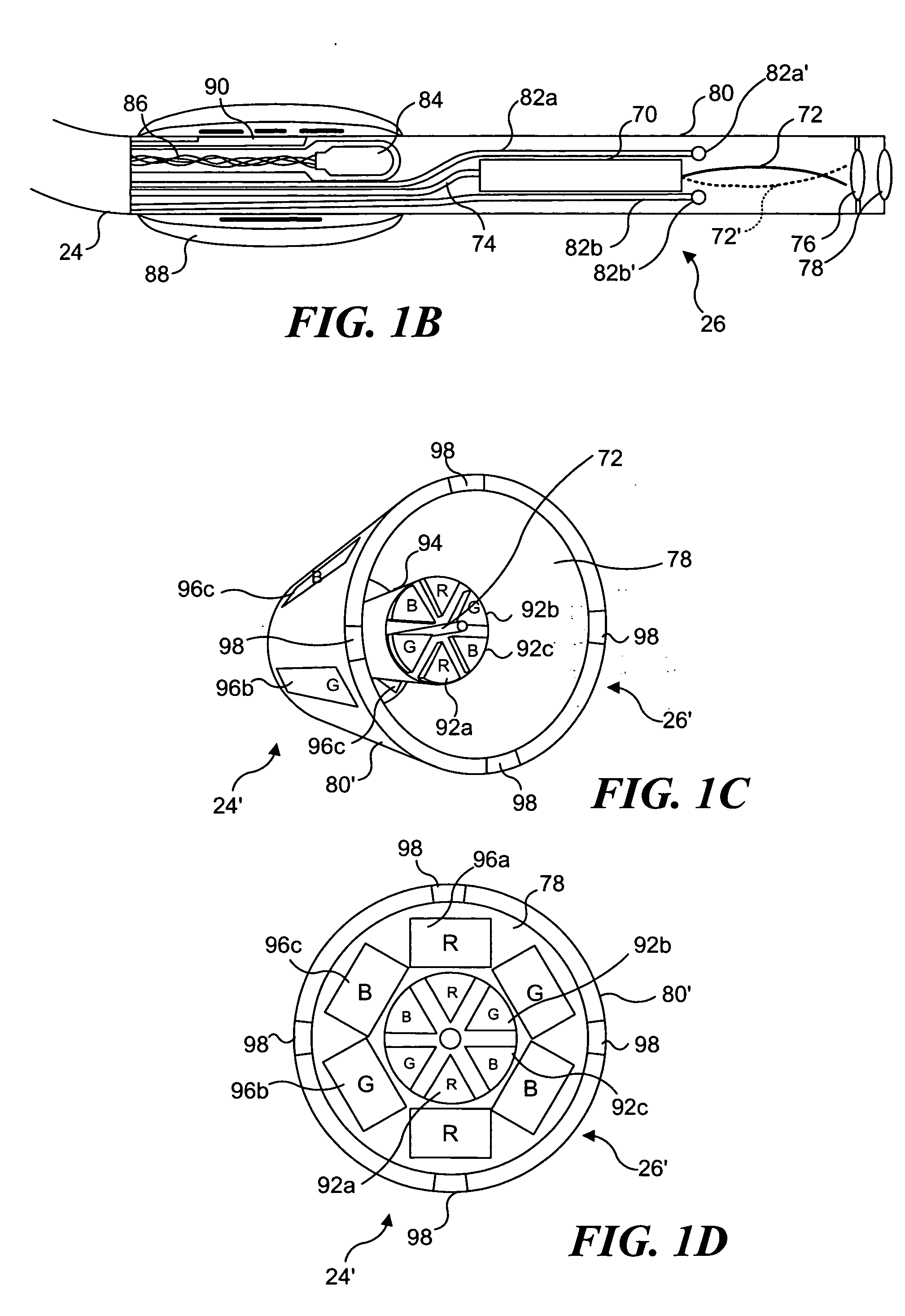
[0012] Accordingly, one aspect of the present invention is directed to a system for visually guiding a flexible endoscope through linked passages within a body. The system includes a signal source that emits a reference signal useful for spatially tracking the progress of the flexible endoscope through the linked passages, and a sensor that produces an output signal indicating a 3-D disposition of a distal end of the flexible endoscope using the reference signal of the signal source. The signal source can either be included adjacent to the distal end of the flexible endoscope or can be disposed external to a patient's body. If the signal source is external, the sensor is disposed adjacent to the distal end of the flexible endoscope, while if the signal source is mounted on the flexible endoscope, the sensor is disposed externally. A user interface is included for displaying a view from within the linked passages as the flexible endoscope is advanced therethrough. The displayed image enables the flexible endoscope to be visually guided and tracked along a path being followed through the linked passages.
[0013] The system preferably employs a 3-D model of the linked passages that is used to assist in determining at least an initial path along which to advance the flexible endoscope. The 3-D model is preferably derived from an image of a portion of a body in which the linked passages are disposed, for example using the images produced by a CT or MRI scan. This model provides an indication of an orientation and a disposition of the linked passages relative to a specific anatomical feature, such as the carina in the lungs, a bone structure, or other known easily identified feature.
[0015] Optionally, the system also includes a body function sensor configured to be disposed adjacent to either the sternum, the thorax, and the mouth of a patient, to monitor one or more of breathing, chest orientation, and the deformation of the lungs of a patient. This sensor produces data that can be employed for updating the 3-D model in regard to changes caused by a body function. Also, the signal from this sensor is useful for determining the disposition of the distal end of the flexible endoscope in regard to the at least one body function, or for gating the flexible endoscope to synchronize with the body function when sensing the position / orientation of the flexible endoscope, thereby minimizing the effect of the body function.

Problems solved by technology

However, these lesions pose a difficult diagnostic problem; because they are small and peripherally disposed in the lung, they are difficult to reach in order to take a tissue sample.
Current bronchoscopes are only able to fit within the relative large branches of the bronchial system.
However, transthoracic needle aspiration can compromise patient health and produce infections.
Unfortunately, transthoracic needle aspiration can compromise patient health and requires prolonged use of imaging systems that impose a substantial financial expense on the patient, and a high time cost on the hospital.
Though still invasive, this method is much safer and is not considered to be traumatizing to the patient, in contrast to the transthoracic needle aspiration method.
Despite this benefit, the large diameter of commercially available bronchoscopes restricts their entrance into small airways where nodules are commonly found, thus requiring the clinician to either steer the forceps / needle / brush blindly or use fluoroscopy to navigate to these regions throughout the lung in hopes that a representative specimen is obtained from the site actually identified as potentially cancerous.
Unfortunately, drawbacks of this method are: (1) maneuvering a catheter in two separate planes is perceptually awkward; (2) images provided by a conventional bronchoscope are unclear or “fuzzy” and it is relatively difficult to see anatomical detail; (3) it is cumbersome to continually adjust the C-arm; (4) the radiation load associated with continued fluoroscopy is detrimental to the health of both the patient and the physician.
Also, position coordinates of the bronchoscope cannot be measured or calculated with a fluoroscope, precluding its integration into any graphic interface and making it difficult to keep a historical record of the path followed by the bronchoscope, should such a record be needed during follow up examinations.
Additionally, an ultra-thin flexible endoscope and position sensor could also be used for navigating through the urethra for an image-guided biopsy of the prostate, which is not possible with conventional endoscopes.

Method used


Image

  • Catheterscope 3D guidance and interface system
  • Catheterscope 3D guidance and interface system
  • Catheterscope 3D guidance and interface system

Examples


Embodiment Construction

Ultra-Thin Flexible Endoscopes

[0052] Ultra-thin flexible endoscopes have been devised for diagnostic imaging of small lumens with diameters similar to regions in the peripheral lung (i.e., with diameters less than 3 mm). A flexible endoscope of this capability has been achieved mainly by reducing the number of fibers contained within the imaging bundle. The disadvantage of this solution is that in removing fibers, the resolution and field of view are greatly diminished. Space restrictions preclude incorporation of a biopsy channel into the design. Although quite thinner than their predecessors, these flexible endoscopes also remain fairly expensive and often break at small bending radii. The poor imaging ability, fragility, expense, and inability to obtain tissue specimens deters the use of this type of bronchoscope for examination of masses in the peripheral lung.

[0053] The development of a 2 mm diameter flexible endoscope in accord with the present invention enables clinicians ...


PUM


Abstract

Visual-assisted guidance of an ultra-thin flexible endoscope to a predetermined region of interest within a lung during a bronchoscopy procedure. The region may be an opacity-identified by non-invasive imaging methods, such as high-resolution computed tomography (HRCT) or as a malignant lung mass that was diagnosed in a previous examination. An embedded position sensor on the flexible endoscope indicates the position of the distal tip of the probe in a Cartesian coordinate system during the procedure. A visual display is continually updated, showing the present position and orientation of the marker in a 3-D graphical airway model generated from image reconstruction. The visual display also includes windows depicting a virtual fly-through perspective and real-time video images acquired at the head of the endoscope, which can be stored as data, with an audio or textual account.

Description

RELATED APPLICATIONS [0001] This application is a divisional application based on prior copending application Ser. No. 11 / 009,699 filed Dec. 10, 2004, which itself is based on provisional application Ser. No. 60 / 529,077 filed Dec. 12, 2003, the benefit of the filing dates of which are hereby claimed under 35 U.S.C. §§ 120 and 119(e).FIELD OF THE INVENTION [0002] This invention generally relates to a method and apparatus for providing three-dimensional (3-D) guidance to a catheterscope or flexible endoscope that is being advanced through a branching lumen in a patient's body, and more specifically, to the use of a 3-D model in connection with a sensor, for determining the disposition and orientation of a flexible endoscope, for visually guiding the flexible endoscope through a series of branching lumens in a patient's body. BACKGROUND OF THE INVENTION [0003] On high-resolution computed tomography (HRCT) scans, potentially cancerous masses appear as radio-opaque nodules. “Screening” H...

Claims


Application Information

Patent Timeline
Patent Type & Authority Applications(United States)
IPC IPC(8): A61B1/04A61B1/06A61BA61B1/00A61B1/267A61B5/06A61B5/08A61B10/00
CPCA61B1/0008A61B1/00172A61B1/2676A61B5/06A61B5/065A61B5/0816A61B5/7285A61B6/541A61B19/5244A61B2019/5251A61B1/005A61B34/20A61B2034/2051A61B2090/3762A61B1/00097A61B1/000096A61B1/00016A61B1/00045A61B1/07A61B5/062A61B5/066A61B5/08
Inventor SOPER, TIMOTHY D.GLENNY, ROBB W.SEIBEL, ERIC J.
Owner UNIV OF WASHINGTON
Why Eureka
Try Eureka