Laser amplifiers with high gain and small thermal aberrations

a laser amplifier and amplifier technology, applied in lasers, laser cooling arrangements, laser details, etc., can solve the problems of reducing the working distance over which the beam can achieve its tightest focus, reducing the brightness of the source, and reducing the beam quality. achieve the effect of high gain and beam quality

Active Publication Date: 2006-07-13
WUHAN HUARAY PRECISION LASER CO LTD
View PDF17 Cites 42 Cited by
  • Summary
  • Abstract
  • Description
  • Claims
  • Application Information

AI Technical Summary

Benefits of technology

[0018] The present invention provides a solid state laser amplifier system which overcomes these limitations in achieving high gain and beam quality by using a combination of thi

Problems solved by technology

These applications have been greatly limited in scope due to the lack of sufficiently compact, low cost, robust laser system technology to move beyond the demonstration phase.
The challenge is achieving sufficiently high gain conditions as prescribed above without compromising laser brightness.
The laser beam quickly goes from diffraction limited TEM00 mode to higher order modes that can not be focused as tightly and thereby reduces the source brightness as well as greatly reducing the working distance over which the beam can achieve its tightest focus.
The conditions of confinement of the exciting pump light to achieve the highest gain conditions increases the heat deposited per unit area and the associated thermal gradients such that the problem of thermal aberrations becomes compounded.
This problem not only limits the extractable gain but also destroys pulse quality by adding long tails to the amplified pulse which as explained above is hig

Method used


Image

  • Laser amplifiers with high gain and small thermal aberrations
  • Laser amplifiers with high gain and small thermal aberrations
  • Laser amplifiers with high gain and small thermal aberrations

Examples


Embodiment Construction

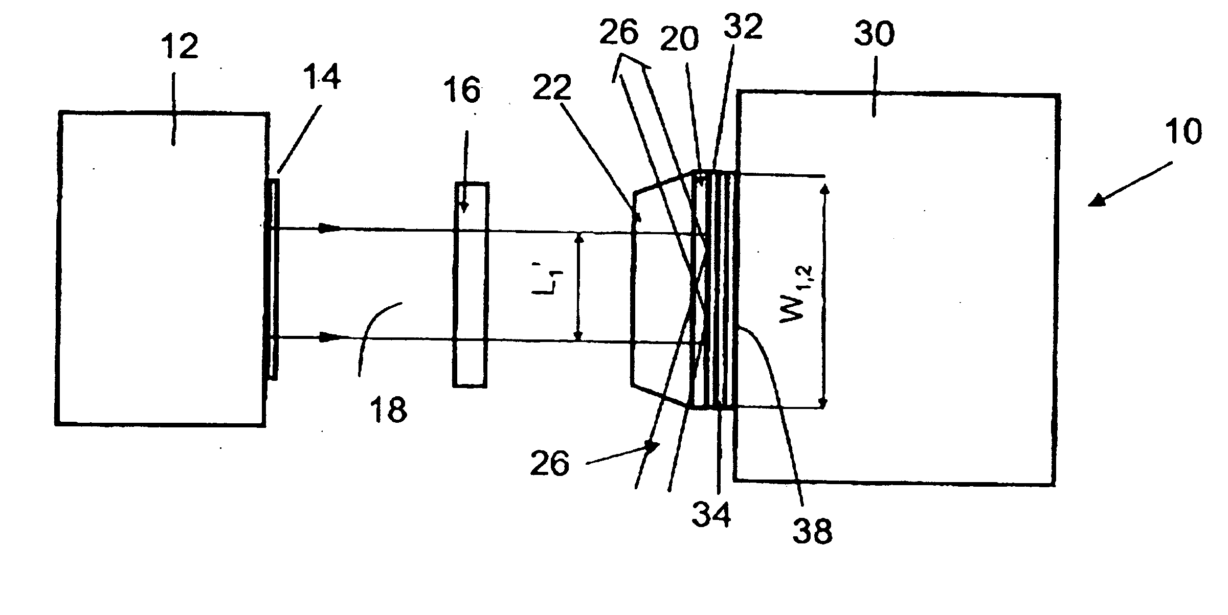
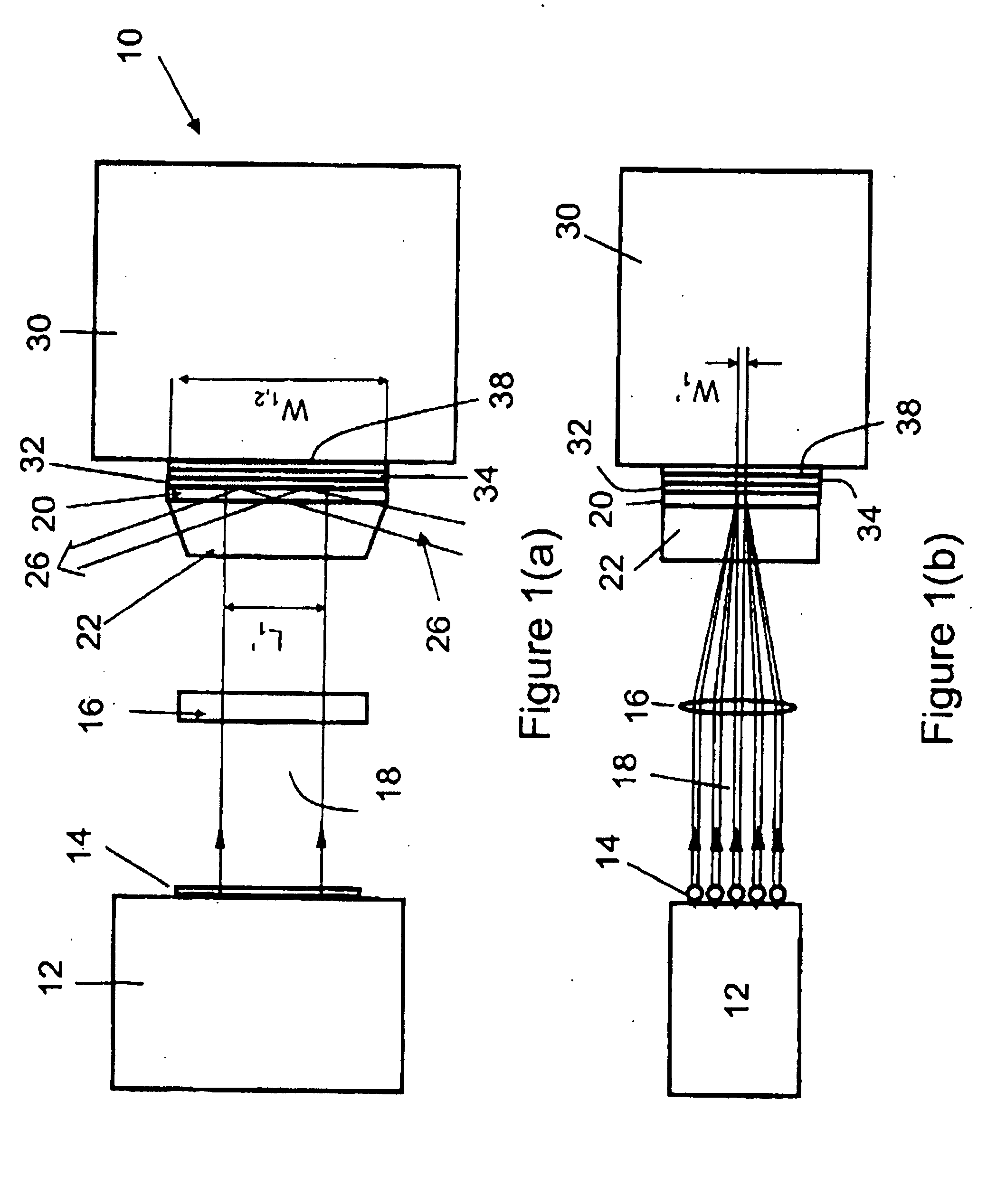
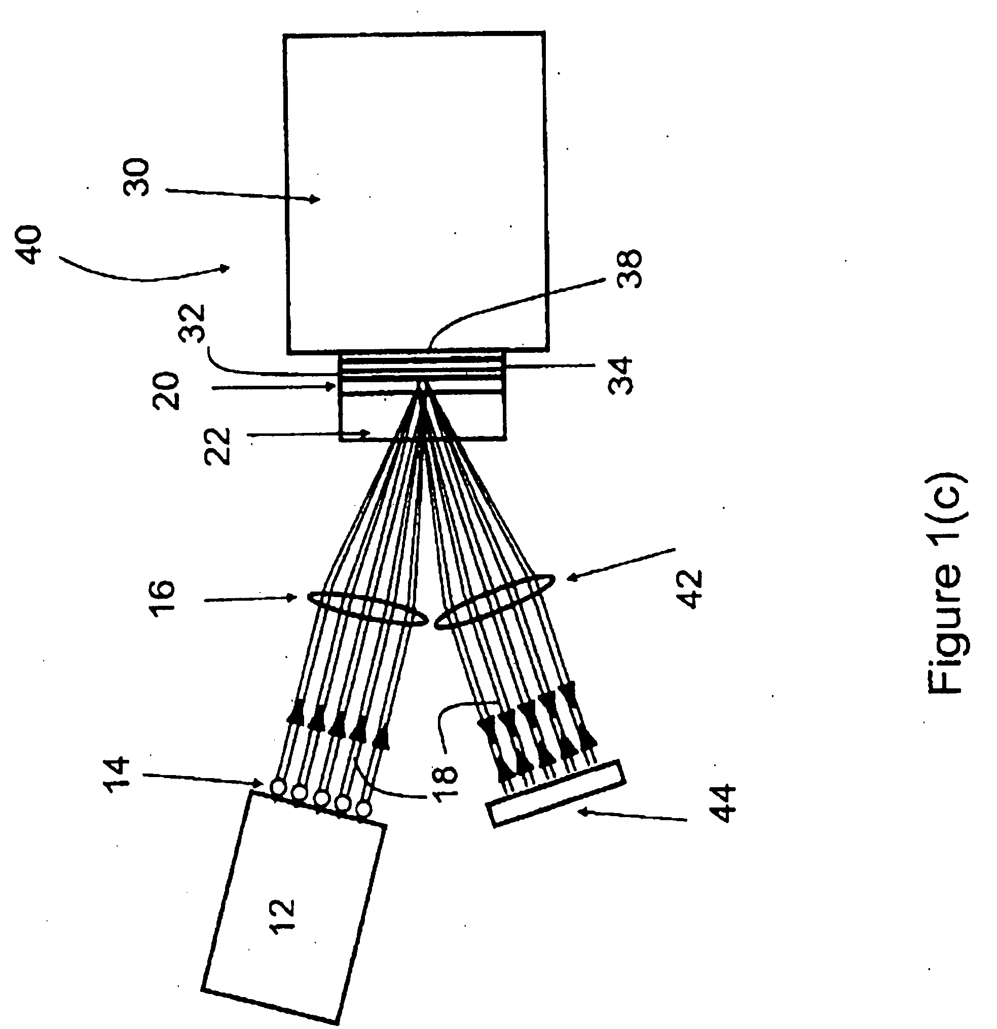
[0040] The present invention provides a solid-state laser amplifier system for amplifying laser pulses. Basic elements of the solid-state laser amplifier system include: 1) a thin active laser solid of thickness t to absorb light from an appropriate light source (the pump) to create the population inversion and associated heat generation within the smallest value of t possible for the desired output power of the device; 2) a pump source comprised of a laser diode or arrays of laser diodes tuned to the maximum absorption of the laser active atom, ion, or molecule; 3) an optical system to transport the pump light to the laser active solid in such a way as to further confine the absorption of light along the two orthogonal directions in the plane of the thin laser active solid; 4) contact of the thin active laser solid to a cooling device with an appropriate material to give good heat transport and high reflectivity of light at the pump and laser wavelengths; 5) a cooling device that m...


PUM


Abstract

The present invention discloses a laser amplifier with high gain and low thermally induced optical aberrations on the amplified laser beam. The amplifier designs allow simple multipass configurations to optimally extract the gain and reduce thermally induced index of refraction aberrations, making it possible to obtain an amplified laser beam of high quality combined with very high overall gains comparable to those achievable with expensive regenerative amplifiers. The amplifier includes a thin active laser solid to create the population inversion and associated heat generation within the thin laser active solid possible for the desired gain value. The system includes a cooling device in thermal contact with the thin active laser solid to provide good heat transport and high reflectivity coatings at the wavelengths of the pump and laser wavelengths. The pump light sources are laser diodes tuned to the maximum absorption of the laser active material. The amplifier also includes an optical system to transport the pump light to the laser active solid in such a way as to further confine the absorption of light along the two orthogonal directions in the plane of the laser active solid in order to get high population inversion and consequently high gains possible.

Description

CROSS REFERENCE TO RELATED APPLICATION [0001] This patent application relates to, and claims the priority benefit from, U.S. Provisional Patent Application Ser. No. 60 / 642,112 filed on Jan. 10, 2005 entitled LASER AMPLIFIERS WITH HIGH GAIN AND SMALL THERMAL ABERRATIONS, filed in English, and which is incorporated herein in its entirety.FIELD OF INVENTION [0002] The present invention relates to solid state laser amplifiers and laser gain modules for high power laser resonators. BACKGROUND OF INVENTION [0003] Compact, efficient, high gain amplifiers and laser resonators are needed in a variety of applications in which one requires high output laser powers in the smallest package possible. These applications include high power free space amplifiers for fibre oscillators [1] and amplifiers for short pulsed laser systems as a means to replace complex regenerative amplifiers [2]. The use of high power and high gain amplifiers enables a new class of compact high peak power and high average...

Claims


Application Information

Patent Timeline
IPC IPC(8): H01S3/04
CPCH01S3/005H01S3/025H01S3/0407H01S3/042H01S3/0604H01S3/0606H01S3/0612H01S3/0615H01S3/0632H01S3/094053H01S3/094057H01S3/094084H01S3/0941H01S3/1611H01S3/1673H01S3/2333H01S3/2341H01S2301/02
Inventor FRANJIC, KRESIMIRHUA, RENZHONGMILLER, R. J. DWAYNE
Owner WUHAN HUARAY PRECISION LASER CO LTD
Why Eureka
Try Eureka