
Applications of the stimulation of neural tissue using light

Inactive Publication Date: 2006-07-13
DECHARMS RICHARD CHRISTOPHER
View PDF79 Cites 264 Cited by
  • Summary
  • Abstract
  • Description
  • Claims
  • Application Information

AI Technical Summary

Benefits of technology

[0009] One advantage of the present invention is that the methods of stimulating neural tissue described herein may be contemplated to be highly specific to individual nerve fibers or small groups of nerve fibers. As intensity of electrical stimulation increases, progressively greater numbers of neurons are activated. This is a physical property of associated with increasing the electrical field size. Optical energy, however, can be confined to a predetermined, physical “spot” size, which is independent of the energy delivered. This physical property is what allows optical techniques to be unique in stimulation of individual or selected neurons. Another advantage of the present invention is the use of the methods of stimulation of neural tissues in vivo. In vitro methods of stimulation, on the other hand, do not lend themselves to the uses of an in vivo method.
[0010] Still another advantage of the present invention is that optical stimulation of neural tissue is not associated with an electrical stimulus artifact. Thus, when optically stimulating individual or multiple neurons stimulated by optical energy, electrical stimulus artifacts are not present.
[0011] Still another advantage of this method is that the use of low energy laser stimulation provides precise localization without tissue contact, resulting in high specificity. Such specificity is of use clinically when nerve stimulation is used for diagnostic applications like identification of subsets of peripheral nerve fibers during operative repair of severed nerves. Also, such technology would allow multiple, focused laser stimuli, to be used to provide functional mapping of neural networks and their interconnections. This advantage may also be applied in therapeutic situations such as neural modulation for pain management, control of movement disorders, and seizure reduction. SUMMARY OF THE INVENTION
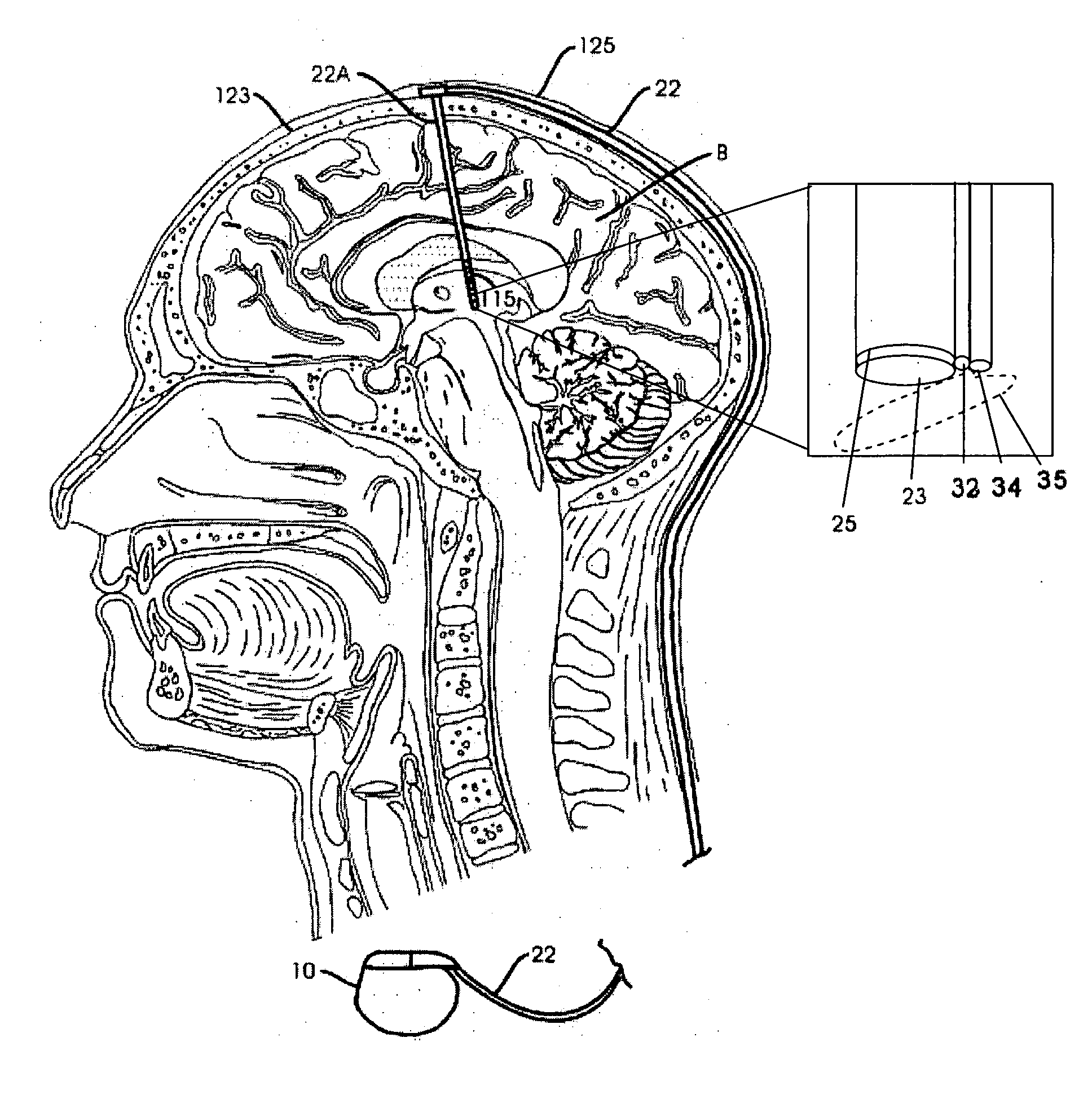
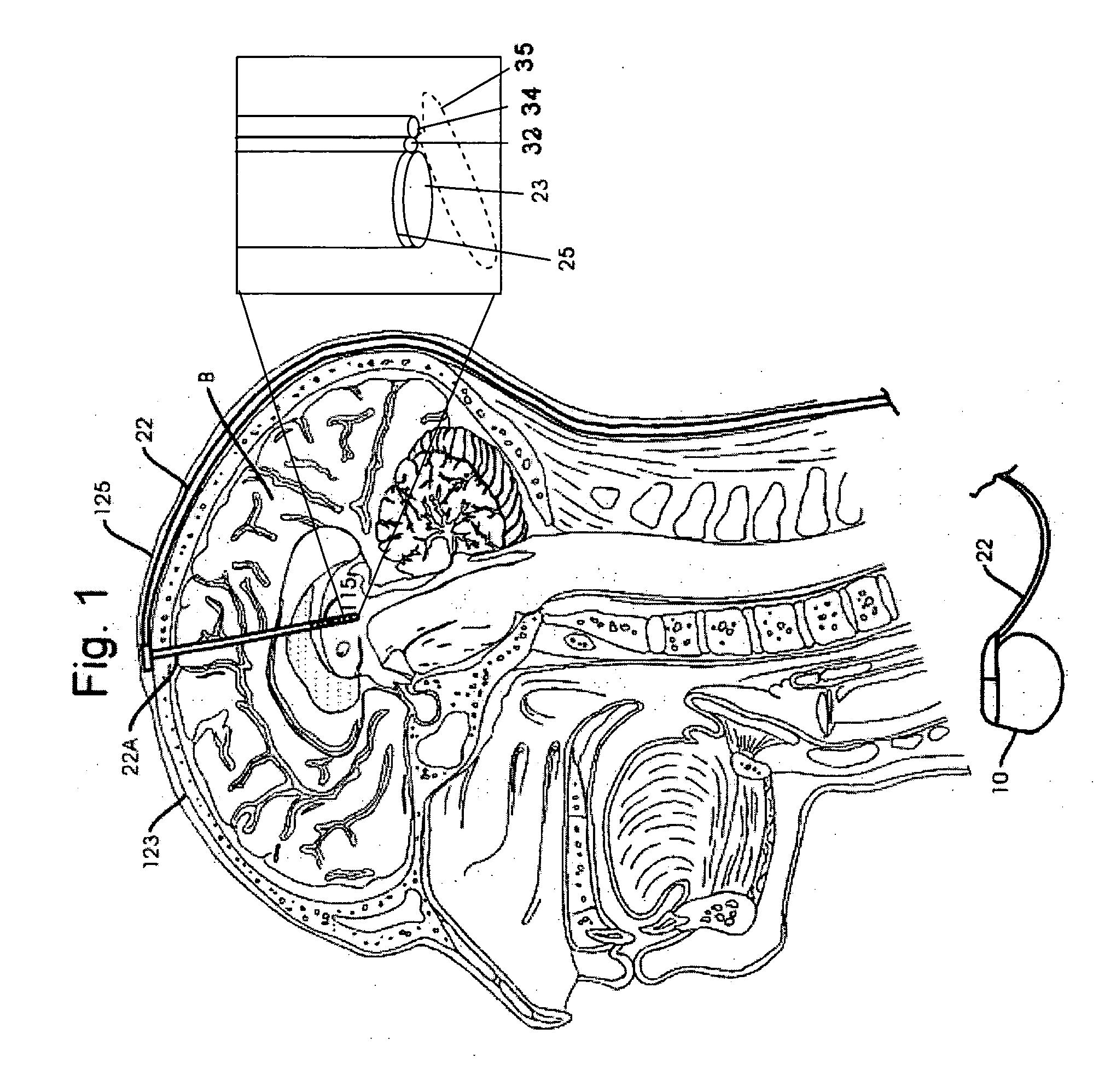
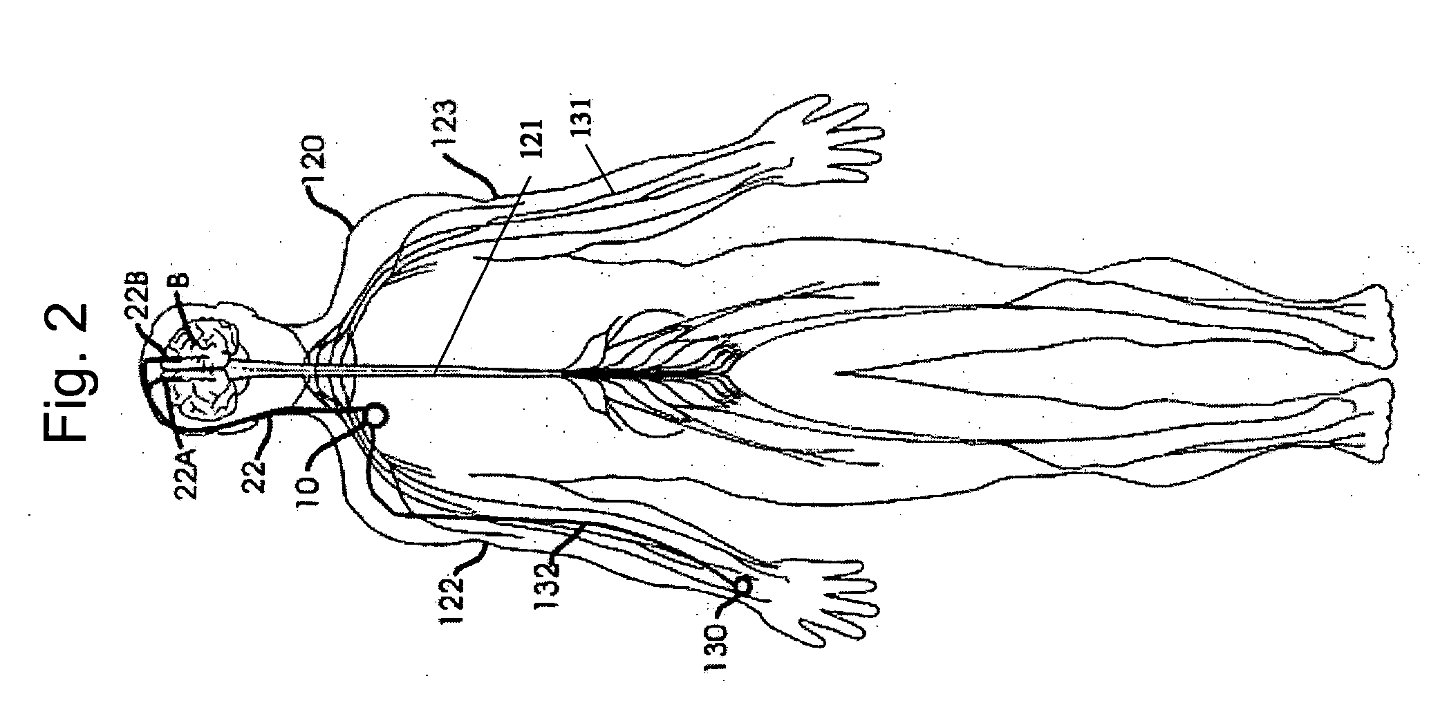
[0012] In one embodiment, the present invention involves a system for stimulating target tissue comprising: a light source for providing stimulation pulses; an implantable light conducting lead coupled to said light source adapted for stimulation of a predetermined site in a subject. In one aspect, the light conducting lead is an optical fiber. In another aspect the light source is a laser. In one aspect, the light source is implantable.
[0013] In one embodiment, the present invention relates to a method of treating a disorder comprising: implanting at least one light-emitter coupled to a light source such that it is in communication with at least one predetermined site in the nervous system of a body; stimulating said at least one predetermined site in said nervous system of said body using said at least one light-emitter. In one aspect of the invention, the disorder being treating is Parkinson's disease, Alzheimer's disease, depression, or epilepsy. In one aspect of the invention, the above method further includes the step of regulating at least one parameter of said step of stimulating, said at least one parameter being selected from the group consisting of pulse width, pulse frequency, and pulse amplitude.
[0014] In one embodiment, the present invention relates to a method for treating a disorder in a patient comprising the steps of: surgically implanting a light-emitter into a brain of a patient wherein said light emitter is coupled to a light source and a signal generator operating said light source; and operating said signal generator to stimulate a predetermined treatment site in said brain.

Problems solved by technology

To name a few, stimulation by such methods may result in nonspecific stimulation of neurons or damage to neurons.
Difficulty exists in recording electrical activity from the neuron due to an electrical artifact created by the stimulus.
Such techniques do not easily lend themselves to implantable electrodes used for long term stimulation of neural tissue.
However, low power lasers are available for uses other than tissue ablation.
The energy required for stimulation large populations of neurons is very small, and the energy required to stimulate an individual neuron is exceedingly small.
In vitro methods of stimulation, on the other hand, do not lend themselves to the uses of an in vivo method.

Method used


Image

  • Applications of the stimulation of neural tissue using light
  • Applications of the stimulation of neural tissue using light
  • Applications of the stimulation of neural tissue using light

Examples


example experimental preparation

[0118] One example of the use of this invention is to use the rat sciatic nerve for frog isolated nerve preparation, as described in U.S. Pat. No. 6,921,413, for the target tissue which may serve as an example of its application. One of ordinary skill in the art understands the differences in the surgical procedure necessary to expose the Rat sciatic nerve. Regarding the stimulation of the Rat sciatic nerve, a wavelength of 4.4 micrometers, and energy of 4.7 mJ, a spot size of 619 micrometers, and a pulse frequency of 2 Hz using the FEL may be used. Optical stimulation may also use an energy of 39 ml, 1.78 mJ, and 2.39 mJ.

[0119] The present invention described herein provides methods of stimulating target tissue with optical energy. In other embodiments, the present invention provides a method of stimulating neural tissue by providing a source capable of generating an optical energy having a wavelength in a range of from 3 micrometers to 6 micrometers at an energy output in a range...


PUM


Abstract

The present invention comprises systems and methods for stimulating target tissue comprising a light source; an implantable light conducting lead coupled to said light source; and an implantable light-emitter. The light source, lead and emitter are used to provide a light stimulation to a target tissue

Description

CROSS-REFERENCE [0001] This application claims priority to No. 60 / 628,258 which is incorporated herein by reference in its entirety.FIELD OF THE INVENTION [0002] The present invention relates generally to methods for stimulation of the nervous system. INCORPORATED BY REFERENCE [0003] All publications and patent applications mentioned in this specification are herein incorporated by reference to the same extent as if each individual publication or patent application was specifically and individually indicated to be incorporated by reference. In particular, the following applications, patents, and non patent references are hereby incorporated by reference for all purposes: U.S. Publication Nos. 20030208245, 20040215286, 20020183817, 20040214790, 20030144709, and 20030181960; U.S. Pat. Nos. 6,921,413 and 5,716,377; and H. G. Sachs, et al., “Retinal Replacement—the Development of Microelectronic Retinal Prostheses—Experience with Subretinal Implants and New Aspects”, Graefe's Arch Clin ...

Claims


Application Information

Patent Timeline
IPC IPC(8): A61N5/06
CPCA61N5/0601A61N5/0622A61N2005/063
Inventor DECHARMS, RICHARD CHRISTOPHER
Owner DECHARMS RICHARD CHRISTOPHER
Learn More