Noise supression circuit

a technology of noise suppression circuit and noise suppression, which is applied in the direction of electric controllers, instruments, ignition automatic control, etc., can solve the problems of increasing error rate, affecting other apparatuses, reducing communication quality, and rippling voltage and noise, so as to reduce the size

Inactive Publication Date: 2006-07-20
TDK CORPARATION
View PDF14 Cites 23 Cited by
  • Summary
  • Abstract
  • Description
  • Claims
  • Application Information

AI Technical Summary

Benefits of technology

[0018] It is an object of the invention to provide a noise suppressing circuit for suppressing common mode noise and normal mode noise in a wide frequency range and for achieving a reduction in size.

Problems solved by technology

Consequently, the power transformer circuit develops a ripple voltage having a frequency equal to the switching frequency of the switching circuit, and noise resulting from the switching operation of the switching circuit.
Such a ripple voltage and noise affect other apparatuses.
When the power-line communications are performed, noise emerges on the power line because of the operations of various electric and electronic apparatuses connected to the power line, which causes a reduction in quality of communications, such as an increase in error rate.
The conventional LC filters have a problem that, since the filters have a specific resonant frequency determined by the inductance and the capacitance, a desired amount of attenuation is obtained only within a narrow frequency range.
However, such an inductance element has a problem that the characteristic thereof becomes close to the characteristic of an air-core inductance element, so that the inductance element is increased in size to implement a desired characteristic.
As a result, the EMI filter has a problem similar to that of the above-mentioned LC filter and has a problem that the number of components is increased and the EMI filter is thereby increased in dimensions.
Therefore, it is difficult to effectively suppress common mode noise and normal mode noise in a wide range of frequencies in this choke coil.
Therefore, it is difficult to effectively suppress common mode noise and normal mode noise in a wide range of frequencies in this noise filter.
As a result, the filter circuit has a problem that the number of components is increased and the filter circuit is thereby increased in dimensions, like the above-mentioned typical EMI filter.
The line filter disclosed in the Published Unexamined Japanese Patent Application Heisei 9-102723 is capable of reducing normal mode noise but not capable of reducing common mode noise.

Method used


Image

  • Noise supression circuit
  • Noise supression circuit
  • Noise supression circuit

Examples


first embodiment

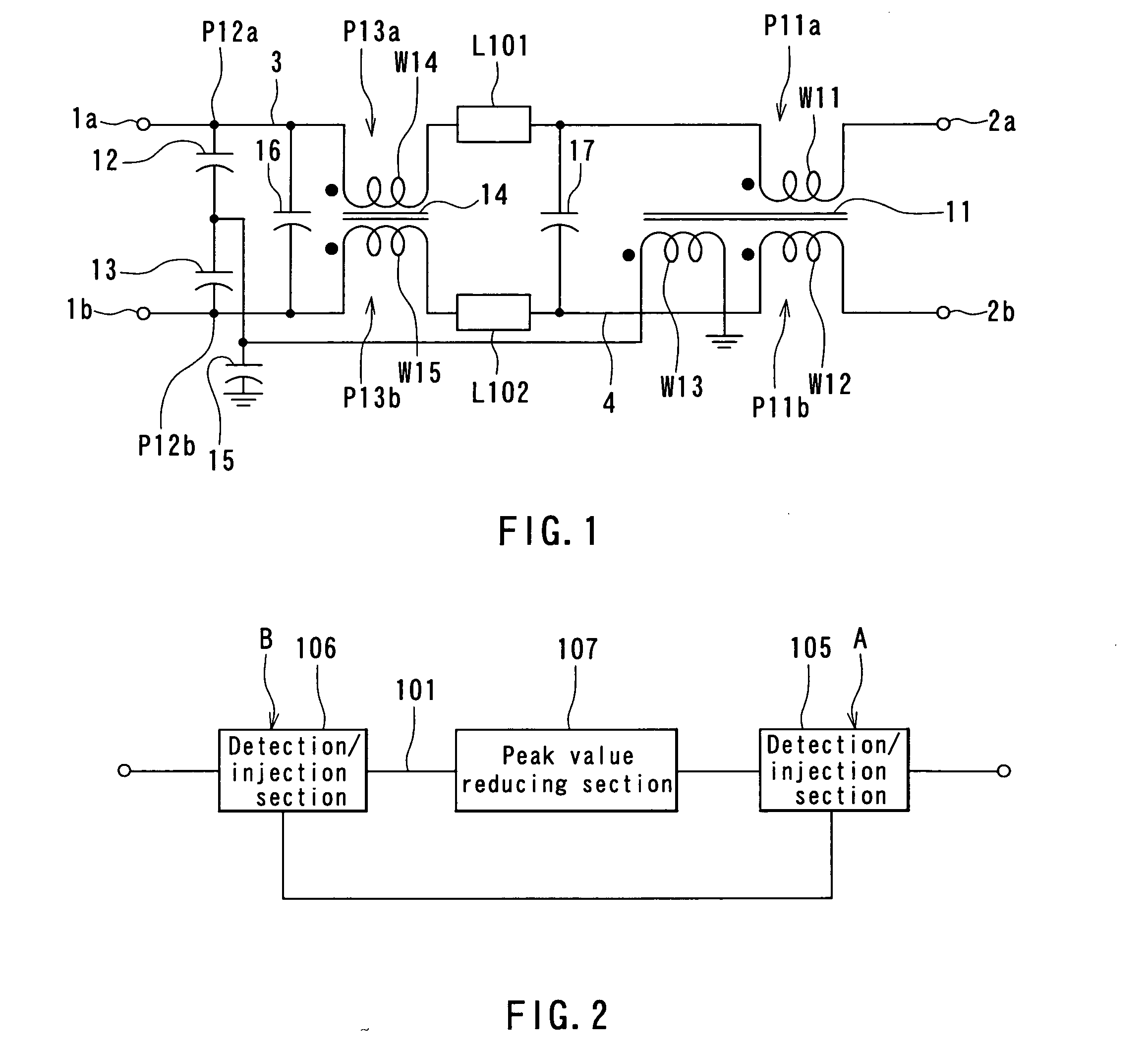
[0052] A noise suppressing technique employed in a first embodiment of the invention will now be described. A cancellation-type noise suppressing circuit is used in the embodiment. Reference is made to FIG. 2 to describe a basic configuration and operation of the cancellation-type noise suppressing circuit.

[0053] As shown in FIG. 2, the cancellation-type noise suppressing circuit comprises: a first detection / injection section 105 connected to a conductor line 101 at a specific point A; a second detection / injection section 106 connected to the conductor line 101 at a point B different from the point A and connected to the first detection / injection section 105 through a path different from the conductor line 101; and a peak value reducing section 107 provided between the first detection / injection section 105 and the second detection / injection section 106 on the conductor line 101.

[0054] Each of the first detection / injection section 105 and the second detection / injection section 106 ...

second embodiment

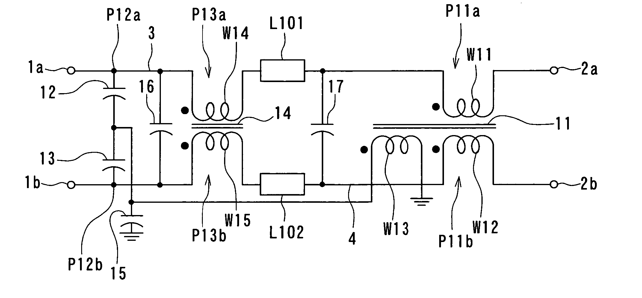
[0137]FIG. 16 is a schematic diagram illustrating the configuration of a noise suppressing circuit of a second embodiment of the invention. The noise suppressing circuit of the second embodiment does not include any peak value reducing section. To be specific, the noise suppressing circuit of the second embodiment has a configuration of the noise suppressing circuit of FIG. 6 from which the fourth winding W14, the fifth winding W15 and the core 14 are excluded and in which the first winding W11 and the second winding W12 are coupled to each other to produce a leakage inductance. The magnetic core around which the windings W11 and W12 are wound may have a shape as shown in FIG. 7 to FIG. 14, for example. In this case, the third winding W13 may be wound around the first magnetic path forming portion that forms the magnetic path allowing a magnetic flux for coupling the windings W11 and W12 to each other to pass.

[0138] The windings W11 and W12 produce a leakage inductance on each of t...


PUM


Abstract

A noise suppressing circuit comprises: windings (W11, W12) inserted to conductor lines (3, 4) at respective points (P11a, P11b) and coupled to each other through a magnetic core (11); a winding (W13) coupled to the windings (W11, W12) through the core (11); capacitors (12, 13) having ends connected to the conductor lines (3, 4) at respective points (P12a, P12b) and the other ends connected to an end of the winding (W13); and windings (W14, W15) inserted to conductor lines (3, 4) at respective points (P13a, P13b) and coupled to each other through a magnetic core (14). These components reduce common mode noise. Capacitors (16, 17) reduce normal mode noise in cooperation with leakage inductances produced by the windings (W14, W15).

Description

TECHNICAL FIELD [0001] The present invention relates to a noise suppressing circuit for suppressing noise propagating through conductor lines. BACKGROUND ART [0002] Power electronics apparatuses such as a switching power supply, an inverter and a lighting circuit of a lighting fixture incorporate a power transformer circuit for transforming power. The power transformer circuit incorporates a switching circuit for transforming a direct current to an alternating current having rectangular waves. Consequently, the power transformer circuit develops a ripple voltage having a frequency equal to the switching frequency of the switching circuit, and noise resulting from the switching operation of the switching circuit. Such a ripple voltage and noise affect other apparatuses. It is therefore required to provide a means for reducing the ripple voltage and noise between the power transformer circuit and the other apparatuses or lines. [0003] LC filters, that is, filters each incorporating an...

Claims


Application Information

Patent Timeline
Patent Type & Authority Applications(United States)
IPC IPC(8): H02H9/06H03H7/09
CPCH03H7/09
Inventor WASAKI, MASARUSAITOH, YOSHIHIRO
Owner TDK CORPARATION
Why Eureka
Try Eureka