
Dielectric ceramic composition and electronic device

a technology of ceramic composition and electronic device, which is applied in the direction of metal-working apparatus, grinding/polishing safety devices, fixed capacitors, etc., can solve the problems of short ir lifetime, reduced specific resistance, and reduced dielectric layers, and achieves improved tc bias characteristics and ir temperature dependence, high specific permittivity, and high capacity

Active Publication Date: 2006-07-20
TDK CORPARATION
View PDF6 Cites 11 Cited by
  • Summary
  • Abstract
  • Description
  • Claims
  • Application Information

AI Technical Summary

Benefits of technology

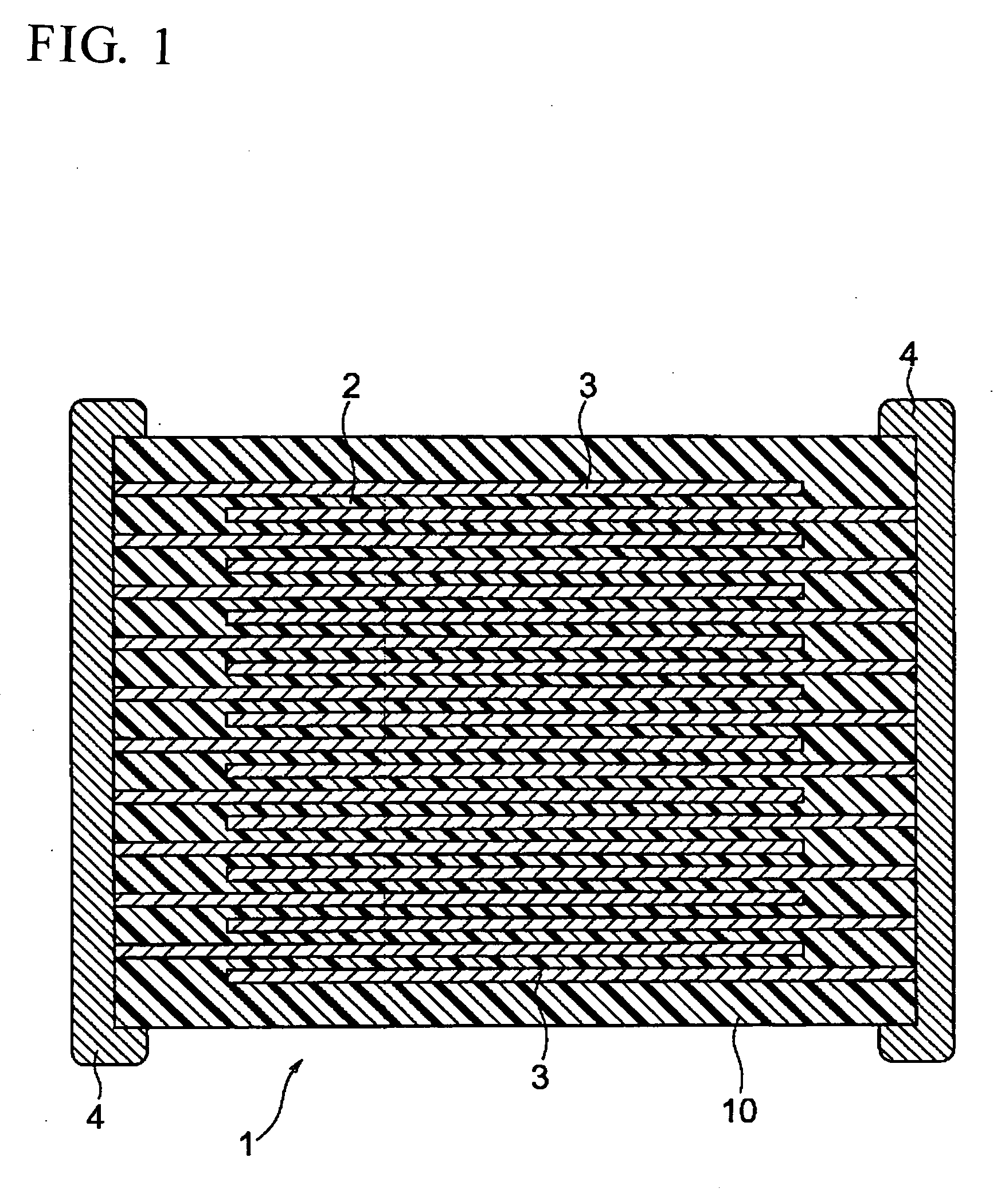
[0011] An object of the present invention is to provide a dielectric ceramic composition having high specific permittivity, capable of maintaining an insulation resistance lifetime and DC bias characteristics (dependency of the permittivity when applied with a direct current voltage), having capacity-temperature characteristics satisfying the X8R characteristics (−55 to 150° C. and ΔC / C=within ±15%) of the EIA standard, able to be fired in a reducing atmosphere, and having improved TC bias characteristics (capacity-temperature characteristics when applied with a direct current voltage) and IR temperature dependency. Another object of the present invention is to provide an electronic device, such as a multilayer ceramic capacitor, particularly able to be formed compact and to have thinner layers and capable of realizing a compact body with a larger capacity by using the dielectric ceramic composition as above.

Problems solved by technology

However, when fired in a reducing atmosphere, the dielectric layers are reduced and the specific resistance declines.
However, a multilayer ceramic capacitor using a reduction-resistant dielectric material has disadvantages that a decline of IR (insulation resistance) due to an application of an electric field is remarkable, the IR lifetime is short and the reliability is low.
Recently, there is a tendency of reducing a wire harness for connecting the electronic apparatus and an apparatus to be controlled thereby and the electronic apparatus may be provided outside of a vehicle, therefore, environments for the electronic devices have been getting more severe.
The dielectric ceramic composition described in the publication satisfies the X8R characteristics, and capacity-temperature characteristic exhibited a usable property in a range of −55 to 150° C. However, the dielectric ceramic composition in the publication has a disadvantage of having poor insulation resistance (IR) temperature dependency and, for example, the insulation resistance (IR) declines in a high temperature environment, so that it becomes difficult to use it under high temperature.
Furthermore, the dielectric ceramic composition in this publication has a disadvantage of having poor TC bias characteristics.

Method used


Image

  • Dielectric ceramic composition and electronic device

Examples


example 1

[0146] First, three kinds of compounds (Ba0.9Ca0.1TiO3, Ba0.8Ca0.2TiO3 and Ba0.7Ca0.3TiO3) including Ba, Ca and Ti and having a perovskite crystal structure expressed by a general formula of ABO3 were prepared as main component materials. In the present example, the three kinds of main component materials were produced by mixing powders of BaCO3, CaCO3 and TiO2 in predetermined amounts so as to obtain the above compositions, respectively, then, performing calcining thereon and milling the results.

[0147] Then, the above three kinds of main component materials were added with Al2O3 (a fifth subcomponent) and later explained first to fourth subcomponents, wet mixed and milled by a ball mill to form slurry, so that dielectric layer paste was fabricated. Note that, in the present example, mole ratio of the above three kinds of main component materials was Ba0.9Ca0.1TiO3:Ba0.8Ca0.2TiO3Ba0.7Ca0.3TiO3=1:1:1. Namely, in the present example, a content of Ca elements was adjusted to 0.2 mole ...

examples 2 to 4

[0178] Other than using Cr2O3 (example 2), GaO2 (example 3) and Ge2O3 (example 4) instead of Al2O3 as the fifth subcomponent, dielectric layer paste was produced in the same way as in the example 1, and capacitor samples 7 to 11 (example 2), 12 to 16 (example 3) and 17 to 21 (example 4) were produced in the same way as in the example 1. The respective characteristics were measured on the obtained capacitor samples in the same way as in the example 1.

TABLE 2TemperatureIRCr2O3CVCharacteristicsTemperatureSampleAmountValueof CapacitanceTc-BiasDependencyNo.Composition Ratio of Main Component Materials (mole ratio)[mole][%][%][%][%] 1*Ba0.9Ca0.1TiO3:Ba0.8Ca0.2TiO3:Ba0.7Ca0.3TiO3 = 1:1:1010−10.9−50.3−3.377Ba0.9Ca0.1TiO3:Ba0.8Ca0.2TiO3:Ba0.7Ca0.3TiO3 = 1:1:10.512.9−11.3−47.5−2.998Ba0.9Ca0.1TiO3:Ba0.8Ca0.2TiO3:Ba0.7Ca0.3TiO3 = 1:1:1113.7−11.8−46.9−2.949Ba0.9Ca0.1TiO3:Ba0.8Ca0.2TiO3:Ba0.7Ca0.3TiO3 = 1:1:1217.5−13.4−41.5−2.710 Ba0.9Ca0.1TiO3:Ba0.8Ca0.2TiO3:Ba0.7Ca0.3TiO3 = 1:1:1319.0−14.1−40...

example 5

[0183] Other than using as the main component materials those obtained by mixing the main component materials shown in Table 5 at mole ratios shown in Table 5, capacitor samples 22 to 26 were produced in the same way as in the sample 3 of the example 1. The respective characteristics of the obtained capacitor samples were measured in the same way as in the example 1. Note that, in this example, contents of Ca elements with respect to 100 moles of ABO3 in the capacitor samples were as shown in Table 5.

TABLE 5CaTemperatureIRAmountAl2O3CVCharacteristicsTemperatureSampleCompositionin ABO3AmountValueof CapacitanceTc-BiasDependencyNo.Ratio of Main Component Materials (mole ratio)[mole][mole][%][%][%][%] 3Ba0.9Ca0.1TiO3:Ba0.8Ca0.2TiO3:Ba0.7Ca0.3TiO3 = 1:1:120114−12.3−45.3−2.9122Ba0.9Ca0.1TiO3:Ba0.8Ca0.2TiO3 = 1:216.7112.1−12.8−46.3−2.8823Ba0.9Ca0.1TiO3:Ba0.8Ca0.2TiO3 = 2:113.3111.7−13.6−47.8−2.8524Ba0.9Ca0.1TiO3:Ba0.8Ca0.2TiO3:Ba0.95Ca0.05TiO3 = 1:1:111.7110.9−14−48.1−2.8325Ba0.9Ca0.1TiO...


PUM

PropertyMeasurementUnit
Fractionaaaaaaaaaa
Fractionaaaaaaaaaa
Substance countaaaaaaaaaa

Abstract

A dielectric ceramic composition comprising a predetermined main component and a fifth subcomponent including an oxide of A (note that A is at least one king selected from a cation element group having an effective ionic radius of 0.065 nm to 0.085 nm at the time of 6 coordination); and the dielectric ceramic composition comprises a plurality of crystal grains including Ca elements and, when assuming that an average value of a concentration of entire Ca exiting in said respective crystal grains is grain Ca concentration, at least unevenness exists in said grain Ca concentration between said crystal grains and it is 5% or higher in a CV value.

Description

BACKGROUND OF THE INVENTION [0001] 1. Field of the Invention [0002] The present invention relates to a dielectric ceramic composition having reduction resistance and an electronic device, such as a multilayer ceramic capacitor, using the dielectric ceramic composition. [0003] 2. Description of the Related Art [0004] A multilayer ceramic capacitor as an electronic device is widely used as a highly reliable compact electronic device having a large capacity and by a large number in one electronic apparatus. In recent years, as the apparatuses become more compact and higher in performance, demands for a multilayer ceramic capacitor to be more compact with a larger capacity, low at cost and higher in reliability have become still stronger. [0005] A multilayer ceramic capacitor is normally produced by using internal electrode layer paste and dielectric layer paste, stacking them by using a sheet method or a printing method, etc. and co-firing internal electrode layers and dielectric layer...

Claims


Application Information

Patent Timeline
IPC IPC(8): C04B35/468
CPCB32B18/00C04B35/4682C04B35/62645C04B35/62685C04B35/6303C04B35/64C04B2235/3203C04B2235/3206C04B2235/3208C04B2235/3213C04B2235/3215C04B2235/3217C04B2235/3224C04B2235/3225C04B2235/3227C04B2235/3229C04B2235/3239C04B2235/3241C04B2235/3256C04B2235/3258C04B2235/3262C04B2235/3286C04B2235/3287C04B2235/3409C04B2235/3418C04B2235/3436C04B2235/3454C04B2235/658C04B2235/6584C04B2235/6588C04B2235/663C04B2237/12C04B2237/40C04B2237/704C04B2237/706H01G4/1227H01G4/30B24B9/14B24B55/12B24B55/00
Inventor ITO, KAZUSHIGESATO, AKIRA
Owner TDK CORPARATION
Learn More