
Method for fabricating semiconductor device

a semiconductor and device technology, applied in the field of semiconductor process, can solve the problems of reducing the yield and reliability of the device, reducing the performance of the electrical connection, and generating many problems, so as to avoid the failure of the device, and reduce the failure rate of the devi

Active Publication Date: 2006-07-27
POWERCHIP SEMICON MFG CORP
View PDF3 Cites 0 Cited by
  • Summary
  • Abstract
  • Description
  • Claims
  • Application Information

AI Technical Summary

Benefits of technology

[0008] In view of the prior art described above, it is an object of the present invention to provide a method for fabricating a semiconductor device, in which problems such as poor performance of the devices, low process yield and device reliability can be avoided.
[0009] Another object of the present invention is to provide a method for fabricating a semiconductor device, in which the native oxide layer can be eliminated to improve the yield and the reliability of the product.
[0019] The present invention performs a thermal treatment in a nitrogen-containing ambient to eliminate the native oxide layer, so as to avoid the problems of undesirable performance of the devices, which further affects the, yield and reliability of the production. Moreover, the present invention may form a buffer layer before the formation of the conductive layer to decrease the aspect ratio so that problems, such as poor step coverage and voids formation in the conductive layer can be prevented.

Problems solved by technology

The formation of the above native oxide layer generates many problems for the subsequent processing.
For example, the native oxide layer may increase the resistance at the contact point and reduce the electrical connection performance.
Thus, the yield and the reliability of the device are compromised.
The above wet cleaning technique utilizes a hydrofluoric acid (HF) solution to eliminate the native oxide layer, and the process is tedious and time-consumable.
In addition, the above in-situ plasma treatment may induce damages on the silicon substrate or the material containing silicon at the bottom of the opening or the trench, while the native oxide layer, which eventually leads to a reduction of the yield of and the reliability of the products, is being removed, .
The native oxide layer may generate many problems for the processing, thereby reducing the yield and reliability of the devices.

Method used


Image

  • Method for fabricating semiconductor device
  • Method for fabricating semiconductor device
  • Method for fabricating semiconductor device

Examples


Embodiment Construction

[0023] One of the embodiments of the present invention will be described below to explain the method for fabricating semiconductor device by illustrating the formation of a memory cell with a trench capacitor. However, the present invention is not limited to this embodiment.

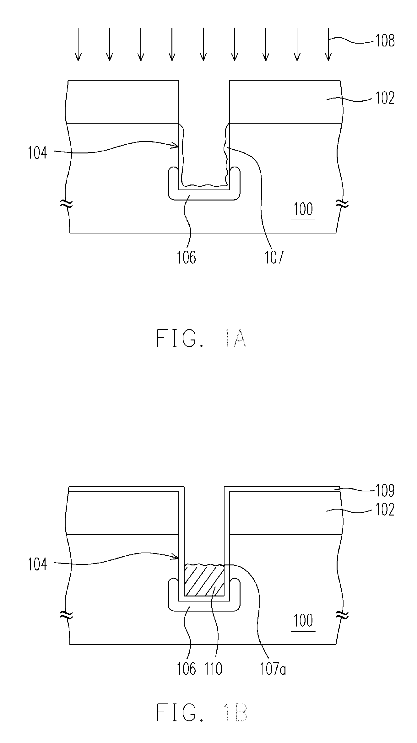
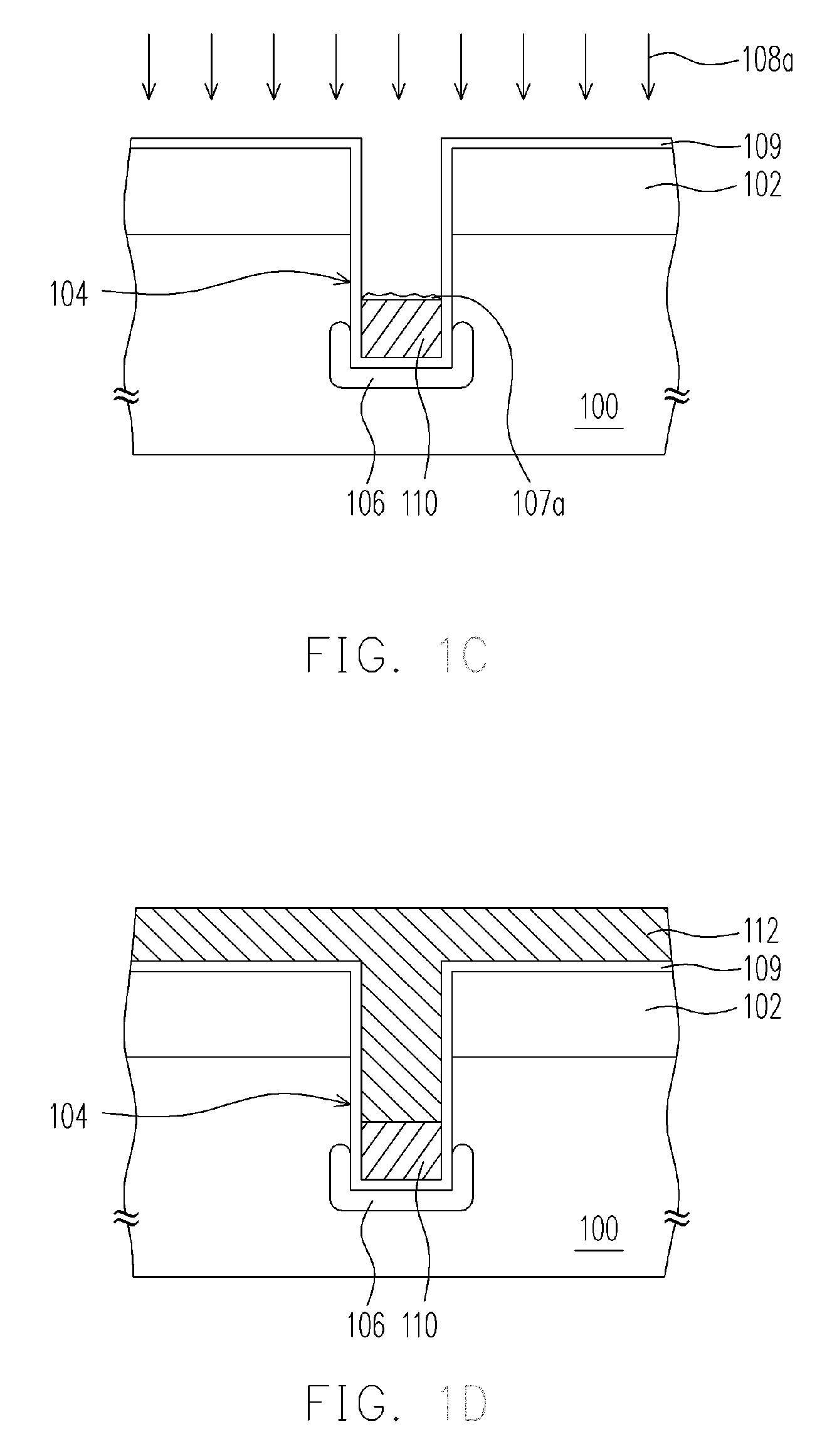
[0024]FIG. 1A to FIG. 1D are schematic, cross-sectional views showing the process flow of the method for fabricating semiconductor device in accordance with one embodiment of the present invention.

[0025] Referring to FIG. 1A, a patterned mask layer 102 is formed on a substrate 100, wherein the material of the patterned mask layer 102 can be, for example, silicon nitride. The steps for forming the patterned mask layer 102 include, for example, forming a mask material layer (not shown in the drawings) by chemical vapor deposition (CVD) to cover the substrate 100, followed by a photolithographing process and a etching process to form patterns in the mask material layer.

[0026] Thereafter, the patterned mask layer ...


PUM


Abstract

A method for fabricating a semiconductor device is described. The method includes providing a substrate having a trench therein, and a trench device in the trench. The trench device includes two gate structures disposed on the sidewalls of the trench, a doped region in the substrate between the gate structures and an inter-gate dielectric layer disposed on the surface of the gate structures. A thermal treatment process in a nitrogen-containing ambient is performed to remove the native oxide layer formed on the surface of the doped region. Then, a conductive layer is formed to fill in the trench.

Description

CROSS-REFERENCE TO RELATED APPLICATION [0001] This application claims the priority benefit of Taiwan application serial no. 94100439, filed on Jan. 7, 2005. All disclosure of the Taiwan application is incorporated herein by reference. BACKGROUND OF THE INVENTION [0002] 1. Field of Invention [0003] The present invention relates to a semiconductor process; more particularly, to a method for fabricating a semiconductor device. [0004] 2. Description of Related Art [0005] In an ordinary integrated circuit processing, the photolithography and etching technology is commonly used for forming an opening or a trench, for example, in a silicon substrate or a material containing silicon. It is well known in the art that, when the wafer is waiting to be delivered to the next chamber after the opening or the trench to be formed in the silicon substrate or the material containing silicon, the silicon substrate or the material containing silicon at the bottom of the opening or the trench is exposed...

Claims


Application Information

Patent Timeline
Patent Type & Authority Applications(United States)
IPC IPC(8): H01L21/44
CPCH01L21/02057H01L21/02068H01L29/66181H01L29/66825
Inventor YOUNG, REXWANG, PIN-YAO
Owner POWERCHIP SEMICON MFG CORP
Learn More