Method of forming a ruthenium thin film using a plasma enhanced atomic layer deposition apparatus and the method thereof

Inactive Publication Date: 2006-08-10
ASM GENITECH KOREA +1
View PDF30 Cites 57 Cited by
  • Summary
  • Abstract
  • Description
  • Claims
  • Application Information

AI Technical Summary

Problems solved by technology

When copper is used for forming interconnecting conductors, copper material has a tendency of being diffused into the surrounding insulation material directly underneath and the sides of the copper wires over time, causing electrical leakage, thereby the characteristics of the electrical system of the interconnecting wires is deteriorated through the leakage.
A ruthenium thin film deposited by using sputtering method has the characteristics of high degree of purity, uniformity and density, but it has a drawback of having poor step coverage, thereby it is not well suited for forming a thin film requiring good step coverage as the width of the integrated circuit patterns is getting tighter and the depth of the trenches is becoming deeper in forming extremely small semiconductor elements.
Therefore, the ruthenium thin films formed by sputtering method has limitations as a diffusion barrier layer for blocking the diffusion of copper material into the neighboring insulation layer and as an adhesion layer between the copper layer and the diffusion layer as well as other applications such as the electrodes of the storage capacitors in dynamic random

Method used


Image

  • Method of forming a ruthenium thin film using a plasma enhanced atomic layer deposition apparatus and the method thereof
  • Method of forming a ruthenium thin film using a plasma enhanced atomic layer deposition apparatus and the method thereof
  • Method of forming a ruthenium thin film using a plasma enhanced atomic layer deposition apparatus and the method thereof

Examples


embodiment 1

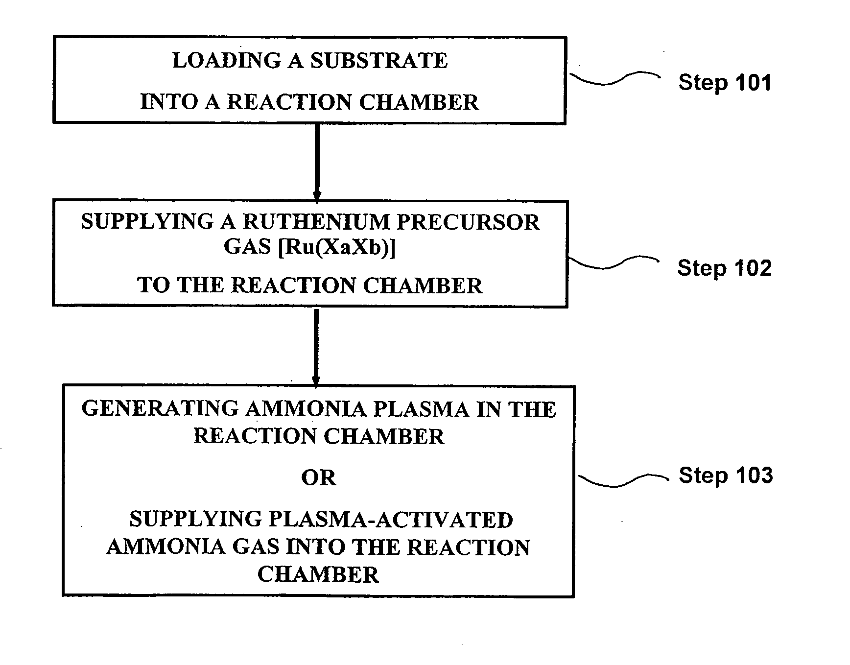
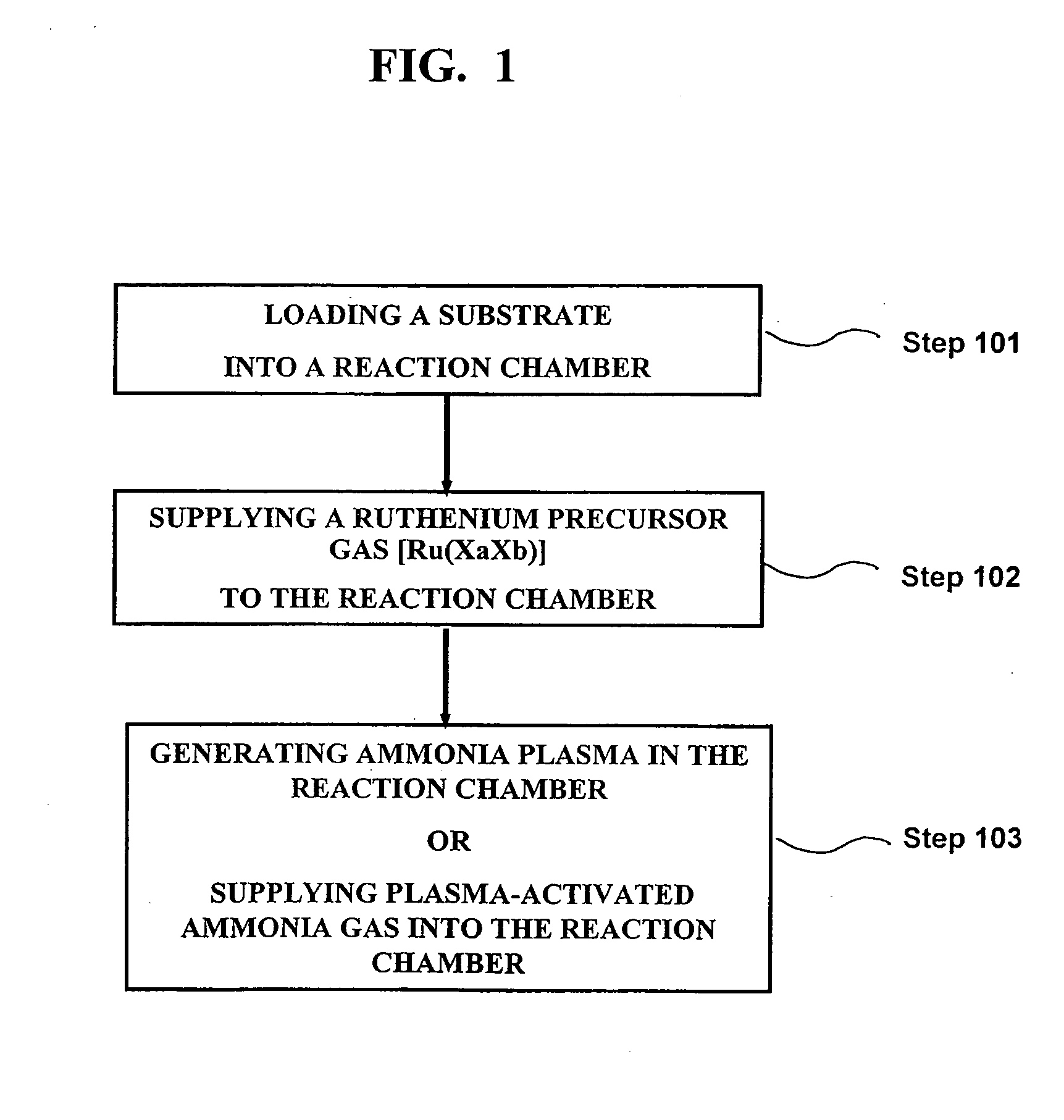
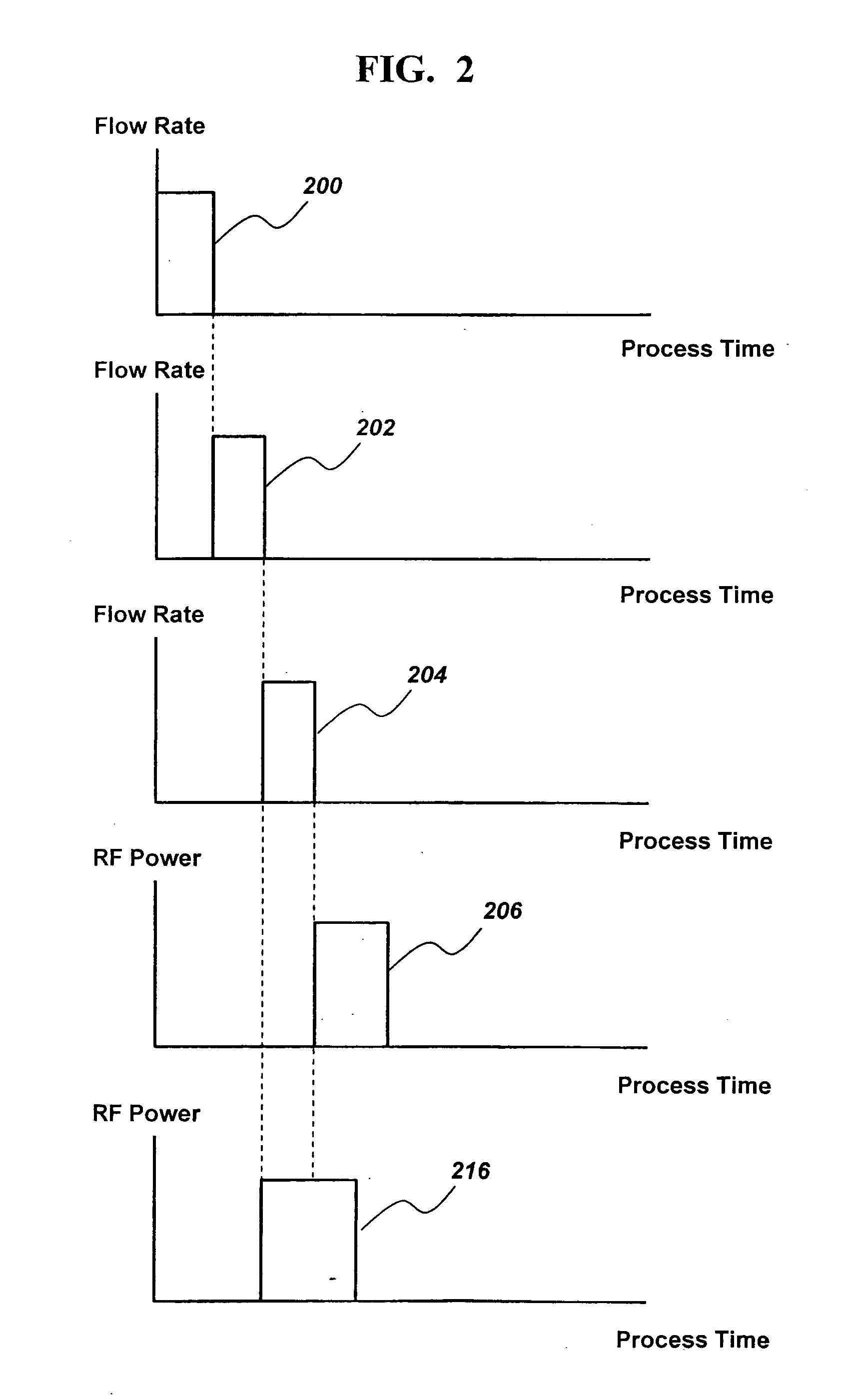
[0056] After the preparation steps described above, referring to FIG. 2, the ruthenium precursor Ru(EtCp)2 in gaseous state 200 is supplied into the reaction chamber for the time duration between 0.02 and 20 seconds, thereby the ruthenium precursor gas is adsorbed onto the surface of the substrate. The ruthenium precursor gas un-adsorbed and remaining in the reaction chamber space is purged by flowing an inert gas 202 for the time duration between 0.1 and 10 seconds, ammonia gas(NH3) as a reactant gas 204 is supplied into the reaction chamber for the time duration between 0.02 and 10 seconds, plasma 206 is generated in the reaction chamber by applying RF power in the reaction chamber for the time duration between 0.02 and 10 seconds so that a ruthenium thin film is deposited on the surface of the substrate, and an inert gas is supplied(not shown) to the reaction chamber to purge the reaction chamber. The above steps are repeated until a ruthenium film layer to a desired thickness is...

embodiment 2

[0057] After following the preparation steps described above, referring to FIG. 2, the ruthenium precursor Ru(EtCp)2 200 in a gaseous state is supplied into the reaction chamber for the time duration between 0.02 and 20 seconds, ammonia gas 202′ is supplied into the reaction chamber for the time duration between 0.1 and 10 seconds in order to purge the ruthenium precursor gas un-adsorbed onto the surface of the substrate and remaining in the reaction chamber space, and while ammonia gas 204′ is continuously flown through the reaction chamber, plasma is generated 216′ in the reaction chamber by applying RF power in the reaction chamber for the duration between 0.02 and 10 seconds to deposit a ruthenium thin film on the surface of the substrate. After the plasma generation period 216′, an inert gas is supplied(not shown) to the reaction chamber to purge the reaction chamber. Alternatively, ammonia gas(NH3) is also used for purging the reaction chamber after the plasma generation perio...

embodiment 3

[0058] After following the preparation steps described above, a gas mixture of nitrogen gas(N2) and hydrogen gas(H2) is used in place of ammonia gas(NH3) as in Embodiment 1.

[0059] The gas mixture of nitrogen gas and hydrogen gas activated by plasma behaves very similarly to the ammonia gas activated by plasma, wherein the gas mixture of nitrogen gas and hydrogen gas does not react with the ruthenium precursor at the temperature lower than 400° C. without activation by plasma, thereby such gas mixture, when activated by plasma, is used as a reactant gas in combination with the ruthenium precursor according to the present invention, and also such gas mixture without activation by plasma is used as a purge gas.

[0060] In this exemplary embodiment, the remaining process conditions used for depositing a ruthenium thin film are the same as the process conditions for Embodiment 1 above.

[0061] After following the preparation steps described above, referring to FIG. 2, the ruthenium precur...


PUM

PropertyMeasurementUnit
Temperatureaaaaaaaaaa
Timeaaaaaaaaaa

Abstract

A method of depositing a ruthenium(Ru) thin film by using readily available ruthenium precursors such as Ru(CP)2 and Ru(EtCP)2, ammonia gas(NH3) as a reactant gas or a purge gas or both, and a plasma enhanced atomic layer deposition(PEALD) apparatus and the method thereof, according to the present invention, is disclosed. Also a gas mixture of nitrogen gas(N2) and hydrogen(H2) is used as a reactant gas or a purge gas or both in addition to ammonia gas in depositing a ruthenium thin film according to the present invention. A ruthenium(Ru) thin film of high density, very pure, very smooth on the film surface and uniform is deposited even at the temperature of the reaction chamber below 400° C. using ammonia gas and a gas mixture of nitrogen gas and hydrogen gas, respectively, as a reactant gas under plasma.

Description

FIELD OF THE INVENTION [0001] The present invention relates to a method of forming a ruthenium(Ru) thin film using a plasma enhanced atomic layer deposition(PEALD) apparatus and the method thereof. BACKGROUND ART [0002] Recently, copper material is being widely used for interconnecting the semiconductor elements on a semiconductor chip, even though aluminum material has been primarily used for the same purpose. When copper is used for forming interconnecting conductors, copper material has a tendency of being diffused into the surrounding insulation material directly underneath and the sides of the copper wires over time, causing electrical leakage, thereby the characteristics of the electrical system of the interconnecting wires is deteriorated through the leakage. In order to reduce the diffusion of the copper material into the surrounding insulation material over time, it is necessary to form a diffusion barrier layer between a copper wire and the surrounding insulation material....

Claims


Application Information

Patent Timeline
IPC IPC(8): C23C16/00
CPCC23C16/18C23C16/45542C23C16/45553C23C16/50
Inventor PARK, HYUNG-SANGKANG, SANG-WON
Owner ASM GENITECH KOREA
Why Eureka
Try Eureka