Rotating body dynamic quantity measuring device and system

a dynamic quantity and measuring device technology, applied in the field of measuring systems, can solve the problems of high cyclic deformation, high cyclic fatigue, and difficult to maintain reliability of wire strain gauges, and achieve the effects of not fatigued, not corroded, and high reliability of measuremen

Inactive Publication Date: 2006-08-17
HITACHI LTD
View PDF7 Cites 15 Cited by
  • Summary
  • Abstract
  • Description
  • Claims
  • Application Information

AI Technical Summary

Benefits of technology

[0006] With this invention, since a semiconductive single crystal is used, the device is not fatigued by a high cyclic load. It is therefore possible to secure a sufficient reliability for a long period of use. Further, since the device is formed of a single crystal and has no grain boundary, it is not corroded under a corrosive environment, allowing for a highly reliable measurement.
[0007] Further, since the rotating body dynamic quantity measuring device using a single crystal semiconductor is very sma

Problems solved by technology

However, since a thin film easily develops a high cyclic fatigue, it is difficult for the wire strain gauge to maintain reliability for a long period when used in applications that cause high cyclic deformations, such as measuring strains and torques of rotating shafts.
That is, the wire strain gauge has not been able to be used in applications that affect human lives and thus require very high reliability, such as automotive drive axels.
Further, in forming a Wheatstone bridge for temperature correction four wire strain gauges need to be attached and their possible peeling and

Method used


Image

  • Rotating body dynamic quantity measuring device and system
  • Rotating body dynamic quantity measuring device and system
  • Rotating body dynamic quantity measuring device and system

Examples


embodiment 1

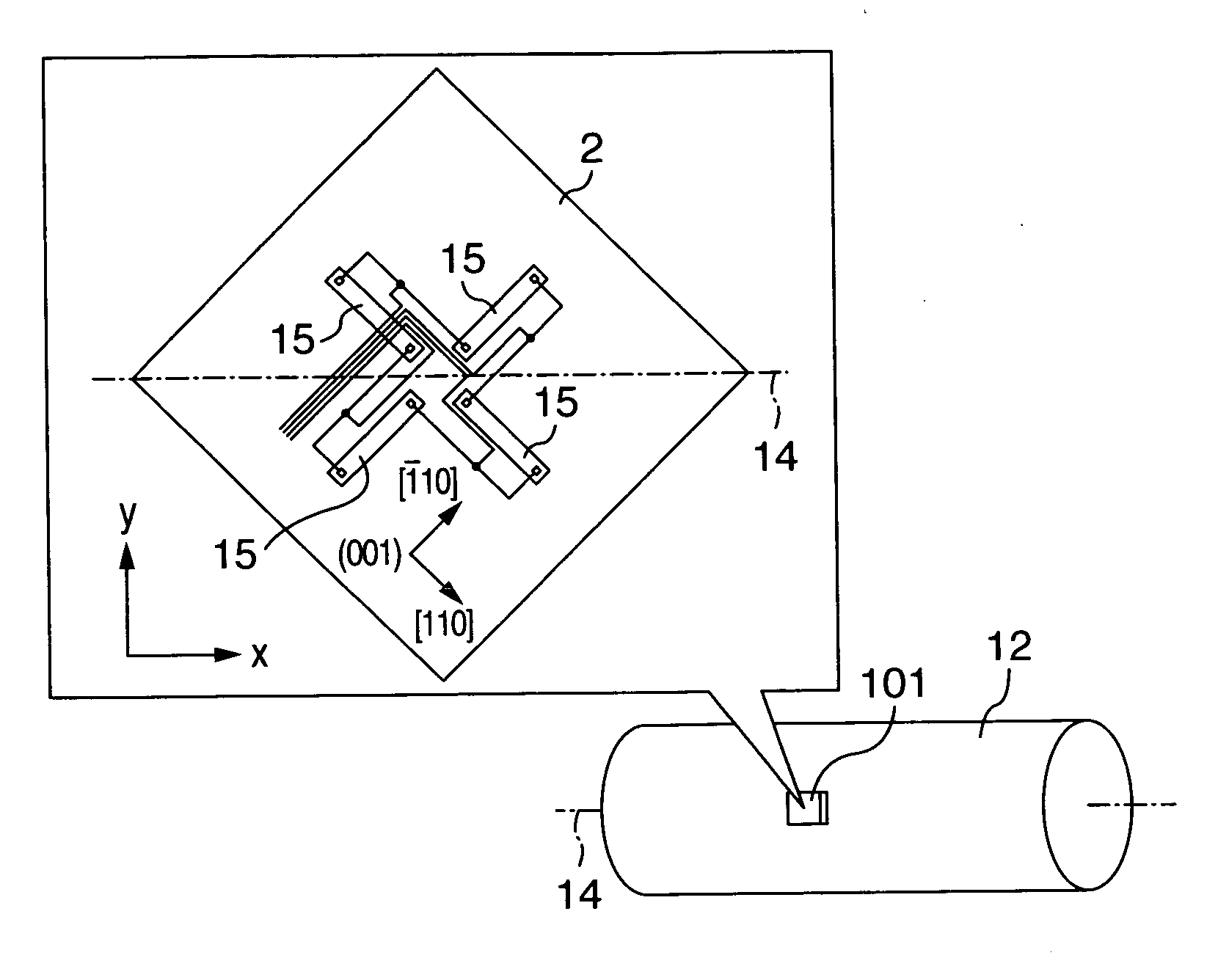
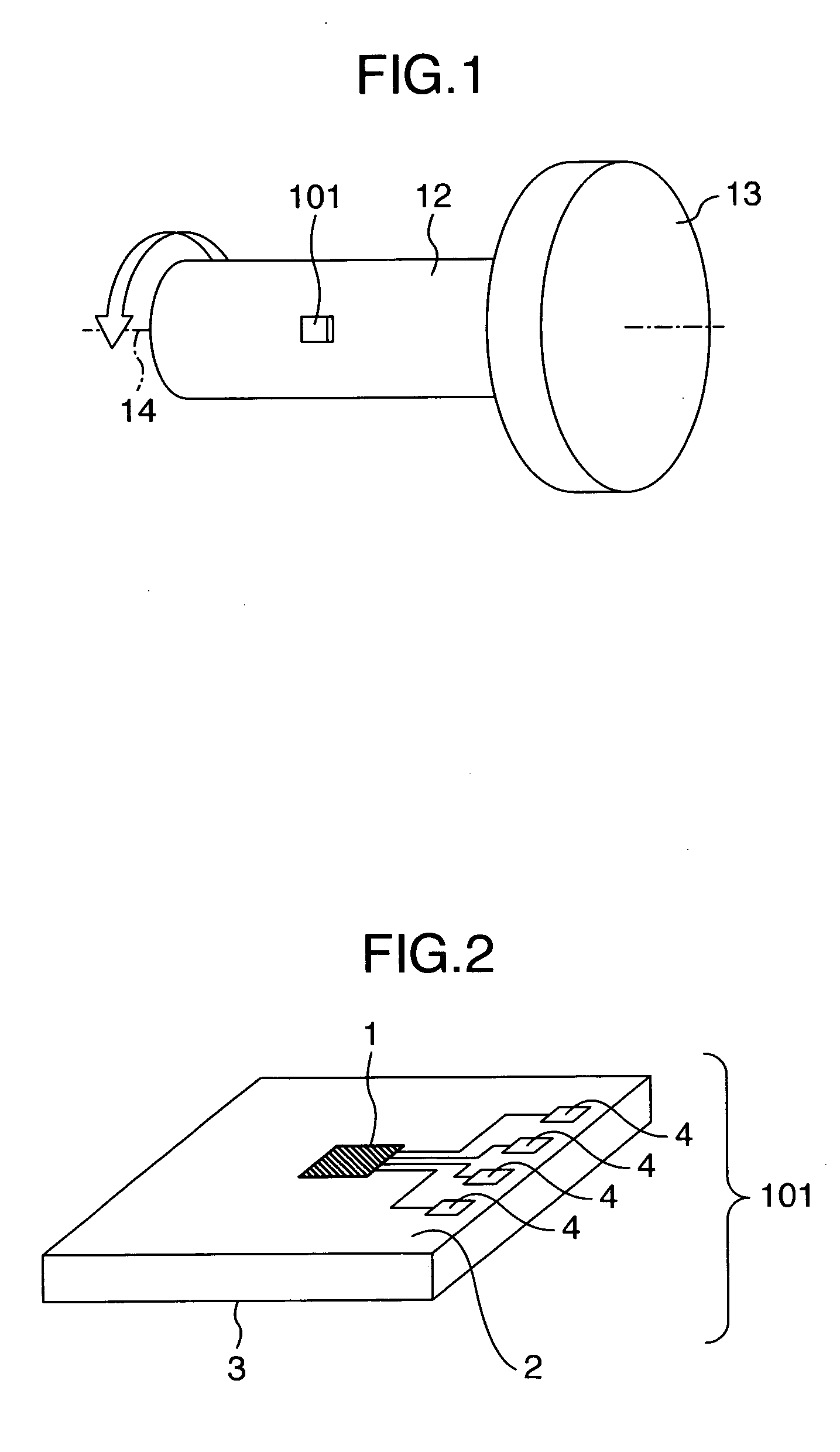
[0044]FIG. 1 shows a construction of a rotating body dynamic quantity measuring system in a first embodiment of this invention. A rotating body dynamic quantity measuring device 101 is installed on a surface of a rotating shaft 12 to measure a torque of the rotating shaft 12 as the shaft 12 rotates about a rotating center 14. The rotating body dynamic quantity measuring device is formed of a single crystal silicon shaped like a square chip which measures several hundred microns to several millimeters in one side and ten microns to several hundred microns in thickness. A back of an element forming surface or a diffusion layer is bonded to the rotating shaft 12 to measure its strains. Normally, in measuring the torque of the rotating shaft, a strain gauge formed of a metal foil is used. However, the metal foil used in the strain gauge has a short fatigue life. So when attached to a rotating shaft that undergoes high cycle deformations, the metal foil cannot withstand a long period of ...

embodiment 2

[0054] The rotating body dynamic quantity measuring device 101 of this invention is manufactured by forming minute, thin film structures several microns in size on the silicon substrate several millimeters square using the semiconductor fabrication process. So it is difficult to visually identify the diffusion layer in the rotating body dynamic quantity measuring device 101. The sensor of this invention considers the direction in which a strain is measured, the crystal orientation, and the direction in which the impurity diffused resistors are arranged. Therefore, what matters in the site of actual use of the rotating body dynamic quantity measuring device 101 is how the device is arranged with respect to the direction in which a strain is to be taken. So, as shown in FIG. 21, a mark 17 is formed in the rotating body dynamic quantity measuring device 101. FIG. 21 shows a rotating body dynamic quantity measuring device using a bridge circuit of a p-type diffusion layer on which an ar...

embodiment 3

[0055]FIG. 25 shows a third embodiment of the rotating body dynamic quantity measuring system according to this invention. FIG. 25 schematically shows the rotating shaft 12 as seen from the end, on the circumferential surface of which is attached a plurality of rotating body dynamic quantity measuring devices 101 with a wireless communication function. Radio waves transmitted from the rotating body dynamic quantity measuring devices 101 are received by a receiving antenna 18 and converted by a receiving unit 19 into strain and torque values. When the rotating shaft 12 is formed of a conductive body such as metal, radio waves do not easily travel to the far side of the shaft. To cope with this problem, this embodiment has a plurality of rotating body dynamic quantity measuring devices 101 attached to the circumferential surface of the rotating shaft to enable measurement at all times. This embodiment offers an advantage that there is no area where strain measurements cannot be taken ...


PUM


Abstract

A single crystal semiconductor including a Wheatstone bridge circuit formed of an impurity diffusion layer whose longitudinal direction is aligned with a particular crystal orientation is connected to a rotating body. A rotating body dynamic quantity measuring device and a system using the measuring device are fatigue- and corrosion-resistant because of the single crystal semiconductor used and are not easily affected by temperature variations because of the bridge circuit considering a single crystal anisotropy.

Description

BACKGROUND OF THE INVENTION [0001] The present invention relates to a measuring system to detect dynamic quantities of a rotating body. [0002] Dynamic quantities of a rotating body, particularly torques, have conventionally been measured by attaching a wire strain gauge to the rotating body and measuring a change in a resistance of a fine metal wire of the gauge. However, since a thin film easily develops a high cyclic fatigue, it is difficult for the wire strain gauge to maintain reliability for a long period when used in applications that cause high cyclic deformations, such as measuring strains and torques of rotating shafts. That is, the wire strain gauge has not been able to be used in applications that affect human lives and thus require very high reliability, such as automotive drive axels. Further, in forming a Wheatstone bridge for temperature correction four wire strain gauges need to be attached and their possible peeling and damage pose a problem of a degraded reliabilit...

Claims


Application Information

Patent Timeline
IPC IPC(8): G01L1/22
CPCG01L1/18G01L1/2293G01L3/10G01L3/108
Inventor OHTA, HIROYUKISUMIGAWA, TAKASHI
Owner HITACHI LTD
Why Eureka
Try Eureka