Methods and apparatus for transmyocardial direct coronary revascularization

a direct coronary revascularization and transmyocardial technology, applied in the field of medical treatment methods and devices, can solve the problems of inability to perform coronary artery bypass surgery, and inability to achieve direct valvular or direct blood flow, and achieve the effect of shortening and thickening, shortening and thickening, and facilitating valving or directing bloodflow

Inactive Publication Date: 2006-08-17
GOWAN L L C
View PDF48 Cites 33 Cited by
  • Summary
  • Abstract
  • Description
  • Claims
  • Application Information

AI Technical Summary

Benefits of technology

[0019] In accordance with the present invention, there is provided a specific TMDCR method wherein a transmyocardial passageway is formed between a chamber of the heart (e.g., left ventricle) and a coronary vein. In this embodiment of the invention, blood may pass from the cardiac chamber, through the transmyocardial passageway, and into the coronary vein for the purpose of improving blood flow to the myocardium and / or to equalize or normalize pressures within the coronary venous vasculature by draining blood from the vein into the cardiac chamber. The coronary vein of this embodiment may be situated next to an obstructed coronary artery, and one or more secondary blood flow passageways may be created between the coronary vein and the adjacent artery, at site(s) which is / are downstream of the coronary artery obstruction. Also, the lumen(s) of the coronary vein and / or adjacent coronary artery may be blocked or embolized at appropriate positions to facilitate the flow of blood in the desired direction(s) through the man-made blood flow passageway(s), the coronary vein and / or the coronary artery. Additionally, one or more valving apparatus may be positioned within the coronary vein and / or within the cardiac chamber, to control or intermittently block the flow of blood through the transmyocardial passageway. ii. TMDCR Procedures Wherein Temporary A-V Fistula is Used to Facilitate Formation of Transmyocardial Passageway Entering Coronary Artery Downstream of Obstruction or Other Intravascular Procedure
[0029] Still further in accordance with the present invention, there are provided stents and stented grafts which are positionable within the transmyocardial passageway, and which protrude into the adjacent coronary vessel (e.g., vein, artery or man-made passageway). These protrusive stents and / or protrusive stented grafts may be self-expanding or pressure-expandable. Optionally, one or more valves or occluder members may be positioned within such protrusive stents and / or stented grafts to facilitate valving or directed movement of bloodflow in accordance with the diastolic / systolic cardiac cycle. ix. Intravascular Valving Apparatus and Methods for Intermittent Coronary Venous Occlusion
[0030] Still further in accordance with the present invention, there are provided intravascular valving devices which are positionable within the coronary sinus, great cardiac vein or other areas of the coronary venous vasculature to control the back pressure within one or more coronary veins in a manner which will result in increased dwell time of the arterial blood within the capillary bed of the ischemic myocardium, and / or dilation of the capillary bed, thereby improving perfusion of the ischemic region(s) of the myocardium.

Problems solved by technology

Such deposits of atherosclerotic plaque tend to fully or partially block the flow of blood through the affected coronary arteries, and if untreated can result in myocardial ischemia, infarction and death.
Such traditional coronary artery bypass surgery is expensive, extremely invasive, and is associated with significant operative and perioperative complications.
However, balloon angioplasty procedures of this type have been associated with a significant incidence of restenosis at the angioplasty site.
Furthermore, these atherectomy or ablative procedures may, in some cases at least, be confounded by the need to meticulously contain and remove the severed fragments of obstructive matter in order to prevent such fragments of obstructive matter from escaping into the patient's circulatory system.
However, the performance of endoscopic surgical procedures of this type typically requires a great deal of operator skill and training.
Thus, many of the drawbacks associated with traditional coronary artery bypass surgery, are also associated with these minimally invasive thoracoscopic procedures.
These TMDCR methods, previously described in U.S. Pat. No. 5,287,861 (Wilk), U.S. Pat. No. 5,409,019 (Wilk) and U.S. Pat. No. 5,429,114 (Wilk), may be difficult or impossible to perform in patients who suffer from total or near total obstructions of a coronary artery, because of the necessary for advancing the catheter through the coronary artery obstruction to accomplish creation of the transmyocardial passageway at a location which is downstream of the coronary obstruction.
Furthermore, because these previously described TMDCR methods require placement of a stent within the transmyocardial passageway, such procedures are necessarily associated with procedural complexities associated with measuring and pre-cutting the stent to a precise length so that it fits within the transmyocardial passageway without protruding into the chamber of the left ventricle and / or the lumen of the coronary artery.
Such repeated flexing and / or stressing of the intramyocardial stent may lead to unwanted migration, dislodgement or damage of the stent.
Because the coronary sinus balloon is typically mounted on a percutaneously inserted catheter and is connected to an extracorporeally located pumping system, the clinical usefulness of these ICSO procedures is presently limited to temporary applications intended to minimize heart muscle damage following infarction or during acute periods of myocardial ischemia.

Method used


Image

  • Methods and apparatus for transmyocardial direct coronary revascularization
  • Methods and apparatus for transmyocardial direct coronary revascularization
  • Methods and apparatus for transmyocardial direct coronary revascularization

Examples


first embodiment

[0116] a. Intravascular Valving Apparatus—

[0117]FIGS. 2, 2a and 2b show a first embodiment of an intravascular valving apparatus 20 which is positioned within the lumen of a coronary blood vessel CBV (artery, vein or man-made passageway), at a location which is adjacent it's intersection with the transmyocardial passageway 10. This embodiment of the valving apparatus 20 has a cylindrical body having an axial bore 24 which extends longitudinally therethrough, and a side aperture 22 formed in the sidewall thereof. The side aperture 22 is preferably the same size or larger than the diameter of the adjacent end of the transmyocardial passageway 10, such that blood flowing from the cardiac chamber (e.g., left ventricle LV) through the transmyocardial passageway 10 will pass directly through the side aperture 22 and into the bore 24 of the valving apparatus 20. An occluder member 26, such as a hinged obturator or pliable elastomeric leaflet is affixed to the cylindrical body of the valvin...

second embodiment

[0120] b. Intravascular Valving Apparatus—Second Embodiment

[0121]FIG. 3 shows a second embodiment of the intravascular valving apparatus 30 which comprises a generally cylindrical body having an axial bore 34 extending longitudinally therethrough and a pair of occluder members 46 positioned therewithin, and a side aperture 32 formed in the cylindrical sidewall of the apparatus 30, behind the occluder members 36. Each occluder member 36 is affixed at least one point to the cylindrical body of the apparatus 30, and may comprise any suitable structure or openable and closeable passage, such as a self-sealing slit or hole, or a hinged leaflet or pliable elastomeric member. The occluder members 46 are alternately moveable between first positions wherein the occluder members 36 directly contact one another so as to prevent blood from backflowing in the backflow direction BD through the axial bore 34 of the apparatus 30, and second positions wherein the occluder members 36 move out of cont...

third embodiment

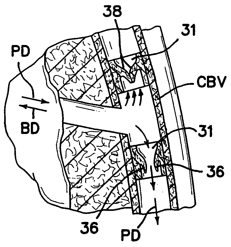
[0126] c. Intravascular Valving Apparatus—Third Embodiment

[0127]FIG. 4 shows a third embodiment of the intravascular valving apparatus 40 which comprises a generally cylindrical body having an axial bore 42 extending longitudinally therethrough and a plurality of occluder members 46 formed therewithin. The cylindrical body and occluder members 46 of this third embodiment of the apparatus 40 are the same as those of the above described second embodiment, except that the cylindrical body of this third embodiment is devoid of any side aperture(s) or openings in the cylindrical sidewall. In contrast to the above described second embodiment 30, this third embodiment of the apparatus 40 is implanted in the lumen of the coronary blood vessel CBV at a location which is downstream of the junction between the coronary blood vessel CBV and the first bloodflow passageway 10.

[0128] It will be appreciated that the individual features and attributes of each of the above-described embodiments of v...


PUM

PropertyMeasurementUnit
elasticaaaaaaaaaa
pressureaaaaaaaaaa
diameteraaaaaaaaaa

Abstract

Methods and apparatus for direct coronary revascularization wherein a transmyocardial passageway is formed between a chamber of the heart and a coronary blood vessel to permit blood to flow therebetween. In some embodiments, the transmyocardial passageway is formed between a chamber of the heart and a coronary vein. The invention includes unstented transmyocardial passageways, as well as transmyocardial passageways wherein protrusive stent devices extend from the transmyocardial passageway into an adjacent coronary vessel or chamber of the heart. The apparatus of the present invention include protrusive stent devices for stenting of transmyocardial passageways, intraluminal valving devices for valving of transmyocardial passageways, intracardiac valving devices for valving of transmyocardial passageways, endogenous tissue valves for valving of transmyocardial passageways, and ancillary apparatus for use in conjunction therewith.

Description

FIELD OF THE INVENTION [0001] The present invention pertains generally to medical treatment methods and devices, and more particularly to methods and devices for transluminal direct coronary revascularization. RELATED APPLICATIONS [0002] This patent application is a continuation-in-part of co-pending U.S. patents application Ser. No. 08 / 730,327, filed Oct. 11, 1996, Ser. No. 08 / 730,496 filed Oct. 11, 1996, and Ser. No. 08 / 837,295 filed Apr. 11, 1997 the entire disclosure of each such related application being expressly incorporated herein by reference. BACKGROUND OF THE INVENTION i. Coronary Artery Disease [0003] Coronary artery disease continues to be one of the leading causes of morbidity and mortality, throughout the world. The typical etiology of coronary artery disease is characterized by the build-up of atherosclerotic plaque within the coronary arteries. Such deposits of atherosclerotic plaque tend to fully or partially block the flow of blood through the affected coronary a...

Claims


Application Information

Patent Timeline
Patent Type & Authority Applications(United States)
IPC IPC(8): A61M39/24A61F2/06A61B17/00A61B17/064A61B17/11A61B17/12A61B17/30A61B17/34A61B18/00A61B18/14A61B19/00A61F2/00A61F2/02A61F2/24A61F2/90A61F2/94A61L27/00A61M25/00
CPCA61B17/00234A61F2220/0008A61B17/0643A61B17/11A61B17/12022A61B17/12045A61B17/12131A61B17/12136A61B17/12172A61B17/3417A61B18/00A61B18/1477A61B18/1492A61B19/38A61B2017/00243A61B2017/00247A61B2017/00252A61B2017/00504A61B2017/1107A61B2017/1135A61B2017/1139A61B2017/12127A61B2017/306A61B2017/347A61B2018/00392A61B2018/1425A61F2/07A61F2/2412A61F2/2418A61F2/2421A61F2/2475A61F2/2493A61F2/90A61F2/94A61F2002/30079A61F2210/009A61M39/24A61M2025/0076A61M2025/1052A61B17/00491A61B90/40
Inventor MAKOWER, JOSHUAFLAHERTY, J. CHRISTOPHERMACHOLD, TIMOTHY R.WHITT, JASON BRIANTUMAS, MARGARET W.LAMSON, THEODORE C.JENSEN, MARC
Owner GOWAN L L C
Why Eureka
Try Eureka