
Four-cylinder, four-cycle, free piston, premixed charge compression ignition, internal combustion reciprocating piston engine with a variable piston stroke

Active Publication Date: 2006-08-24
SUSTAINABLE ENERGY TECH DEV TRUST
View PDF12 Cites 67 Cited by
  • Summary
  • Abstract
  • Description
  • Claims
  • Application Information

AI Technical Summary

Benefits of technology

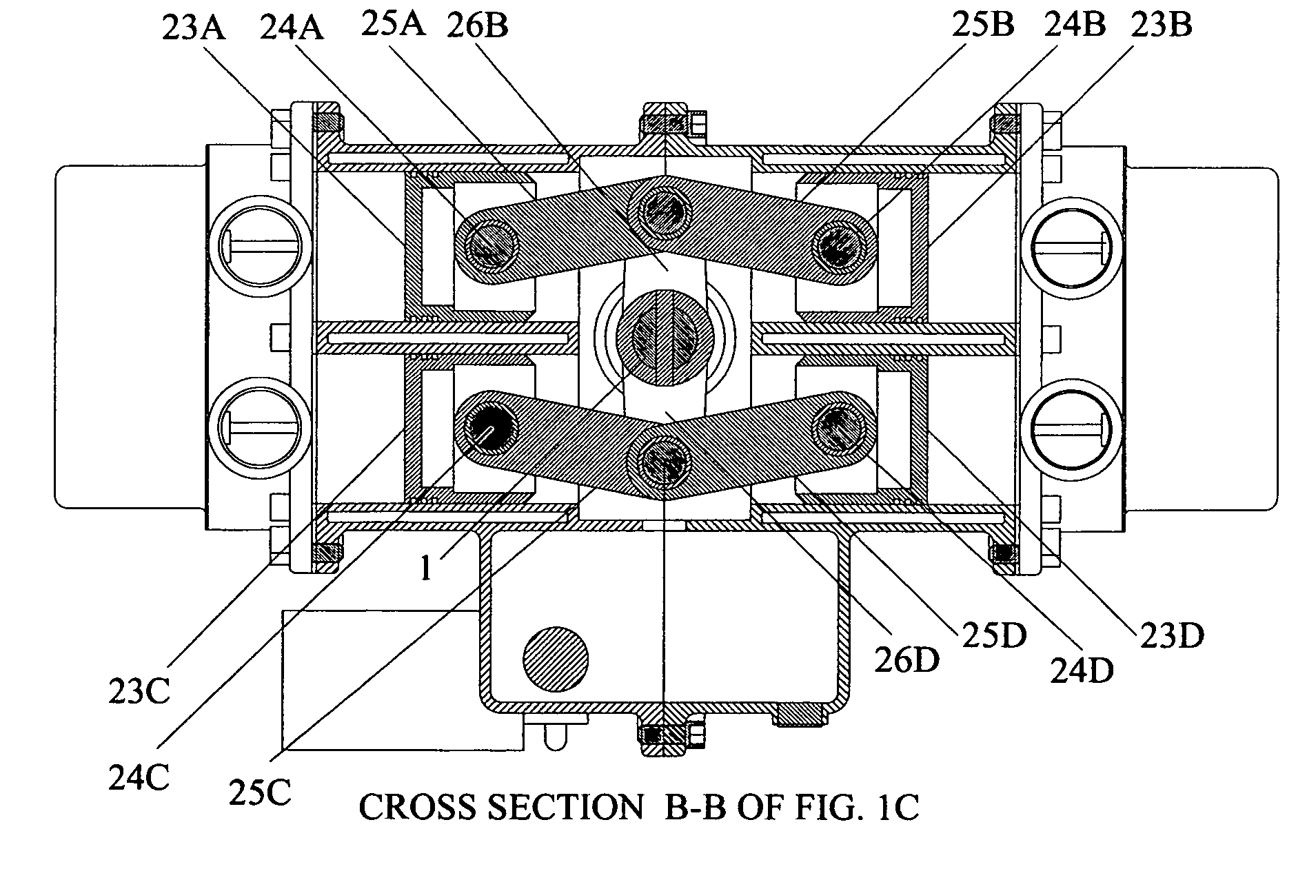
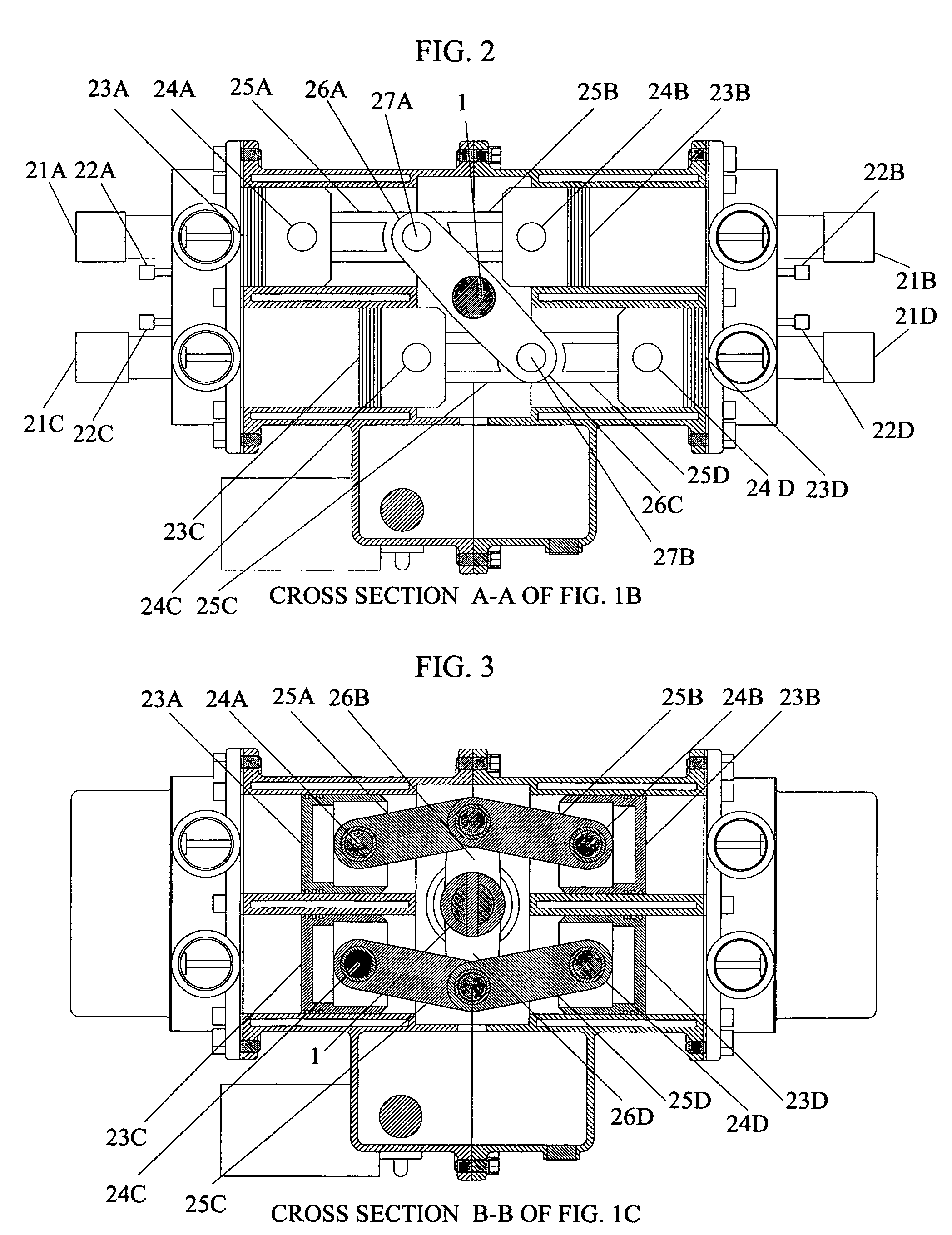
[0045] The preferred floating stroke mechanism, for direct extraction of power from the FPFS engine, is either a linear oscillating shaft, as shown in FIGS. 10A & 10B, or a pivoting shaft with rocker arms, as shown in FIGS. 1-8, for attaching the piston connecting rods. In the former configuration of the FPFS the concurrent linear motion of two oscillating piston pairs can be used to directly drive a variable displacement piston pump or compressor or linear alternator. Or, in the latter, linear oscillation of the piston pairs can be converted to a pivoting (or rocking) shaft output. This pivot shaft does not rotate but instead oscillates clockwise then counterclockwise making a partial rotation with each engine cycle. A pivoting shaft with two sets of rocker arms is used to join two piston pairs with each other, such that the motion of one piston pair is opposite that of the other piston pair (as opposed to the piston pairs moving concurrently in the former arrangement). The length of rocker arms from the pivot shaft is made sufficiently long such that the stroke of the pistons is not limited by the rocker arm throw. Note: In the four-cylinder FPFS engine (as in conventional four-cylinder engines), each of the compression, expansion, exhaust and intake cycles are present at any given time, in one cylinder or the other. The expansion cycle of one cylinder drives the compression cycle of another. Thus, the length of piston travel is always constrained by the pressure of a compression cycle. The stroke length of the other pistons, for example in the exhaust cycle, is determined by the ignition event in the cylinder then in a compression stroke. The compression ignition is a function of a series of engine and charge parameters, which will vary to some extent from cycle to cycle. Thus, the stroke length of any given cycle is indeterminate until charge ignition occurs. Each piston compression stroke length is independent of the other and the piston motion is almost completely free of mechanical stroke length limitations. The mechanisms disclosed by this invention allow the stroke length to vary, or “float”, according to the compression ratio required to ignite the charge of each compression cycle, fully independent of any other cylinders compression stroke. The pistons, if not constrained by the charge pressure of a compression cycle (normally followed by charge ignition), would ultimately stop against the cylinder head.
[0046] As has already been demonstrated by existing free piston PCCI engines, very high compression ratios can also be attained, which improves engine efficiency and can accommodate the characteristics of many different fuels. Very lean fuel mixtures may be utilized, resulting in low emissions. This is also the case with the present FPFS engine. True premixed charge compression ignition, similar to that attained by linear piston engines, or in laboratory tests using a rapid compression-expansion machine, can be attained in the present FPFS engine. In many applications an oscillating shaft can be effectively used to extract power from the engine, as disclosed herein. We note however that, the requirements of some applications are better met by using rotary motion. The preferred means for obtaining rotary motion from the present FPFS engine is to use it as a gas generator for a power turbine. Free piston engines, of both the Otto and Diesel cycles, that use a turbine to extract energy from the engine, have been previously produced, as noted in the Background of the Invention section herein. However, the present FPFS PCCI / HCCI engine with power turbine energy extraction is unique. Both means of power extraction, directly from the oscillating shaft and / or pivoting shaft, as shown in FIGS. 14 & 15, as well as from a power turbine, as shown in FIGS. 16-20, are disclosed herein as a part of the present FPFS invention.
[0049] The electric power producing variations of the FPFS engine herein disclosed are particularly well suited to a number of emerging technologies, as well as traditional applications. For example: distributed generation has not historically been as widely employed as could be possible with the improved efficiency of the FPFS engine. Automotive vehicles (including hybrids) could substantially benefit from the present FPFS engine as well. Also, many common applications, including engine driven pumps and compressors could benefit from the FPFS engine by virtue of lower fuel consumption, lower emissions and fuel flexibility.
[0050] Small aircraft propulsion could benefit from the FPFS engine, as there are currently underway extensive efforts to replace the high-octane fuels used in existing spark ignited reciprocating engines with Diesel or Jet fuel powered engines. The multi-fuel capability of the FPFS engine, and its lower fuel consumption, make it a viable contender for a wide range of aviation propulsion applications. It is also possible that some existing gas turbine applications, such as small turbo-prop or rotary wing aircraft, could be more economic in operation, if designed around the present FPFS engine. The power turbine variant of the present FPFS engine would be the most preferred embodiment of this invention in aircraft applications.
[0052] Small engine powered tools such as chain saws and lawn mowers are further viable candidates for the present FPFS engine. A key element of this application is low cost electronic control. Nonetheless, for such a high volume engine it is anticipated the control could be reduced to an economic single microchip.

Problems solved by technology

As previously noted, with two-cycle linear free piston PCCI / HCCI engines there are inherent constraints on the operating speed range and throttle turn down is limited.
However, the four-cycle PCCI engine, as developed to date, requires highly complex controls that are dictated by the fixed compression ratio associated with the typical crankshaft configuration used in these engines.
If an exhaust valve were to open prior to the expansion cycle in the cylinder sufficiently driving the compression cycle in another cylinder to the ignition point of the charge, then the continuous operation of the engine would fail.

Method used


Image

  • Four-cylinder, four-cycle, free piston, premixed charge compression ignition, internal combustion reciprocating piston engine with a variable piston stroke
  • Four-cylinder, four-cycle, free piston, premixed charge compression ignition, internal combustion reciprocating piston engine with a variable piston stroke
  • Four-cylinder, four-cycle, free piston, premixed charge compression ignition, internal combustion reciprocating piston engine with a variable piston stroke

Examples


Embodiment Construction

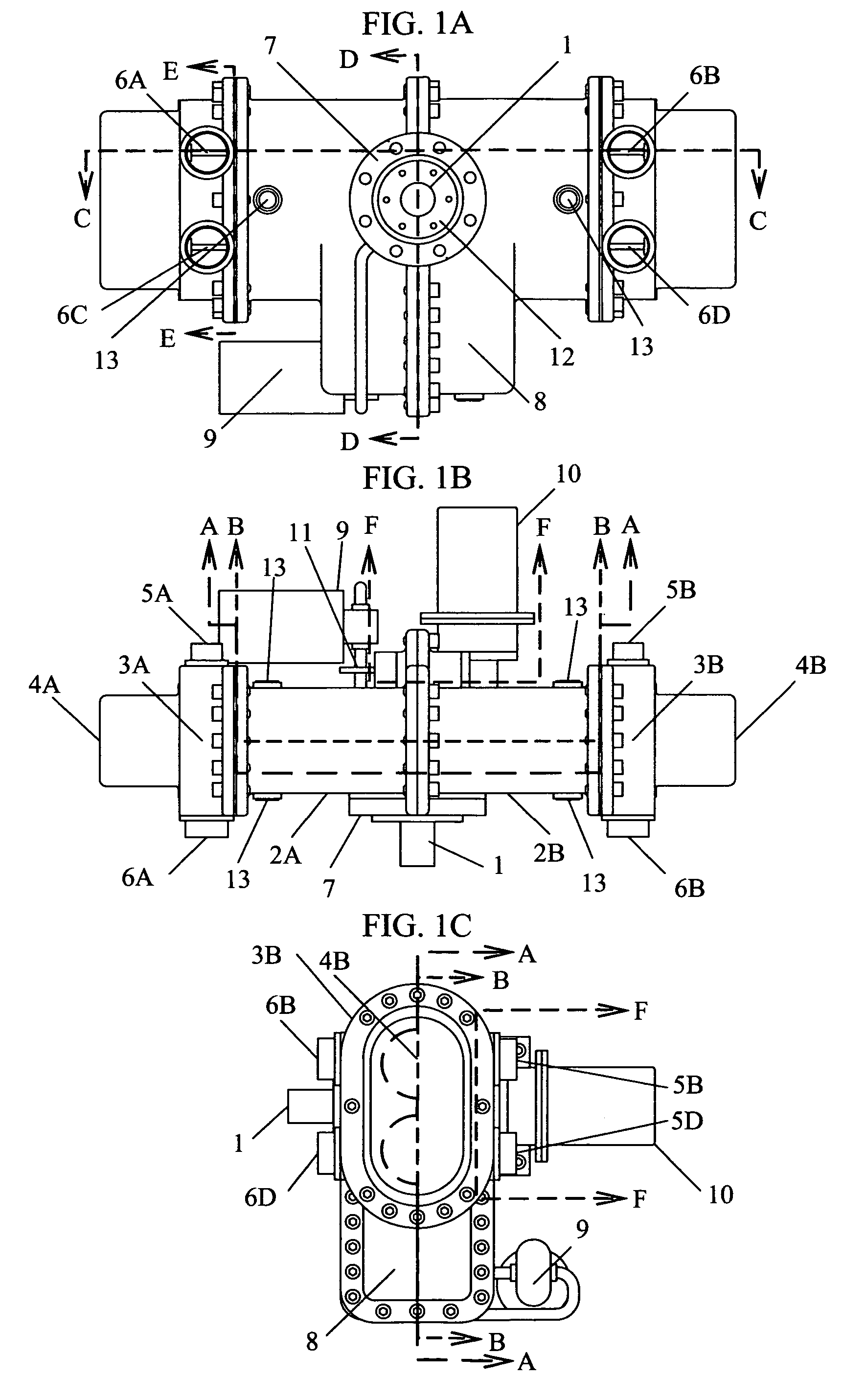
[0096] Facilitating premixed charge compression ignition in an internal combustion reciprocating piston engine, with the objective of improving engine efficiency and lowering emissions-while avoiding the complexities, sensitivities and cost penalties of existing PCCI / HCCI designs-are the criteria for using the four-cycle, four-cylinder, free piston engine configuration for this invention. The application of PCCI / HCCI to a four-cycle, four-cylinder, free piston engine is unique. As will be disclosed herein, there are multiple engine geometries that can achieve the previously cited objectives, and provide various embodiments of the present invention. Thus, FIGS. 1-10 and FIGS. 16-20 illustrate a number of preferred embodiments of the present invention with varying piston arrangements and power extraction strategies. FIGS. 1-7 show a “flat” four-cylinder block 2, with the pistons 23, connected via connecting rods 25, of varying types, to a pivot shaft 1, which provides for direct power...


PUM


Abstract

A four-cycle, four-cylinder, premixed charge compression ignition internal combustion reciprocating free piston engine with a variable piston stroke and a compression ratio that varies as needed to provide charge ignition, to offer the potential of higher efficiency, lower emissions, and multi-fuel operation. The engine does not have a crankshaft, and therefore does not provide direct rotary output. Instead its free pistons oscillate, in a manner similar to a two cycle free piston engine. For many applications, such as piston pumps and compressors, the engine provides an output directly driven by the oscillating pistons. In other applications, such as but not limited to use as a gas generator for a power turbine, the engine provides an indirect means of producing rotary power. When the engine is used with high-speed power turbines, the power turbine may be directly coupled to a high-speed alternator for electrical power output.

Description

CROSS-REFERENCE TO RELATED APPLICATIONS [0001] The benefit of Provisional Application No. 60 / 656,458, filed Feb. 24, 2005 by the same named inventor, entitled “Four cycle, premixed charge compression ignition, free-piston, internal combustion reciprocating engine with a floating (variable) stroke” and of substantially the same subject matter, is hereby requested.FEDERALLY SPONSORED RESEARCH OR DEVELOPMENT [0002] Not Applicable COMPACT DISC APPENDIX [0003] Not Applicable BACKGROUND OF THE INVENTION [0004] This invention relates to the field of engines, specifically to a four-cycle, four cylinder, free-piston, premixed charge compression ignition, internal combustion reciprocating piston engine with a variable piston stroke that offers the potential of enhanced efficiency, lower emissions, and multi-fuel operation. Applications include but are not limited to, use with automotive vehicles, engine driven pumps, engine driven compressors, small aircraft, marine vehicles, and power tools....

Claims


Application Information

Patent Timeline
IPC IPC(8): F02B75/22F02B71/00
CPCF01B9/047F02B1/12F02B71/00F02B75/04F02B75/228F02B75/24F02D15/02F02D41/0002F02D41/0007F02D41/187F02D41/3035F02D2041/001Y02T10/12Y02T10/128F02D35/028
Inventor FITZGERALD, JOHN WILLIAM
Owner SUSTAINABLE ENERGY TECH DEV TRUST
Learn More