Laser system with short pulse characteristics and its methods of use

a laser system and short pulse technology, applied in the field of laser systems, can solve the problems of thermal damage laterally and axially into the clear layer in addition to the pigmented layer, local mechanical damage in addition to thermal damage to adjacent tissues, and achieve the effect of conciliating thermal effects

Active Publication Date: 2006-08-24
IRIDEX CORP
View PDF14 Cites 46 Cited by
  • Summary
  • Abstract
  • Description
  • Claims
  • Application Information

AI Technical Summary

Benefits of technology

[0028] In another embodiment of the present invention, a laser treatment system includes a diode pump source that pumps a frequency doubled solid state visible laser. The frequency double solid state visible laser produces a pulsed output. A controller sy

Problems solved by technology

In these applications the energy is absorbed by chromophores such as melanin or blood and conducts away from the absorbing or pigmented layers into adjacent non-absorbing and non-exposed layers—thus causing thermal damage laterally and axially into the clear layers in addition to the pigmented layers.
The chromophore is heated to damaging levels and in certain cases will boil or explode—causing local mechanical damage in addition to the thermal damage to adjacent tissues.
Physicians have not used gr

Method used


Image

  • Laser system with short pulse characteristics and its methods of use
  • Laser system with short pulse characteristics and its methods of use

Examples


example 1

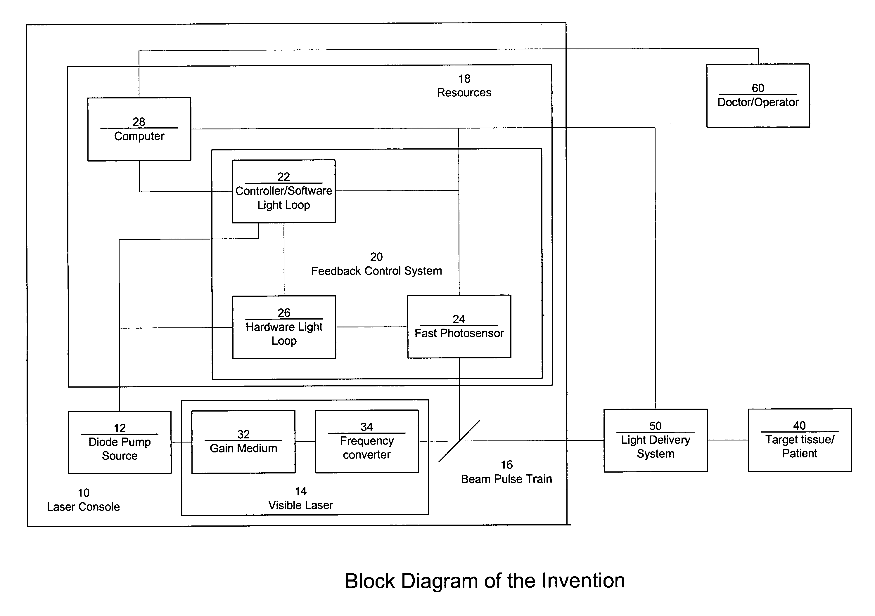
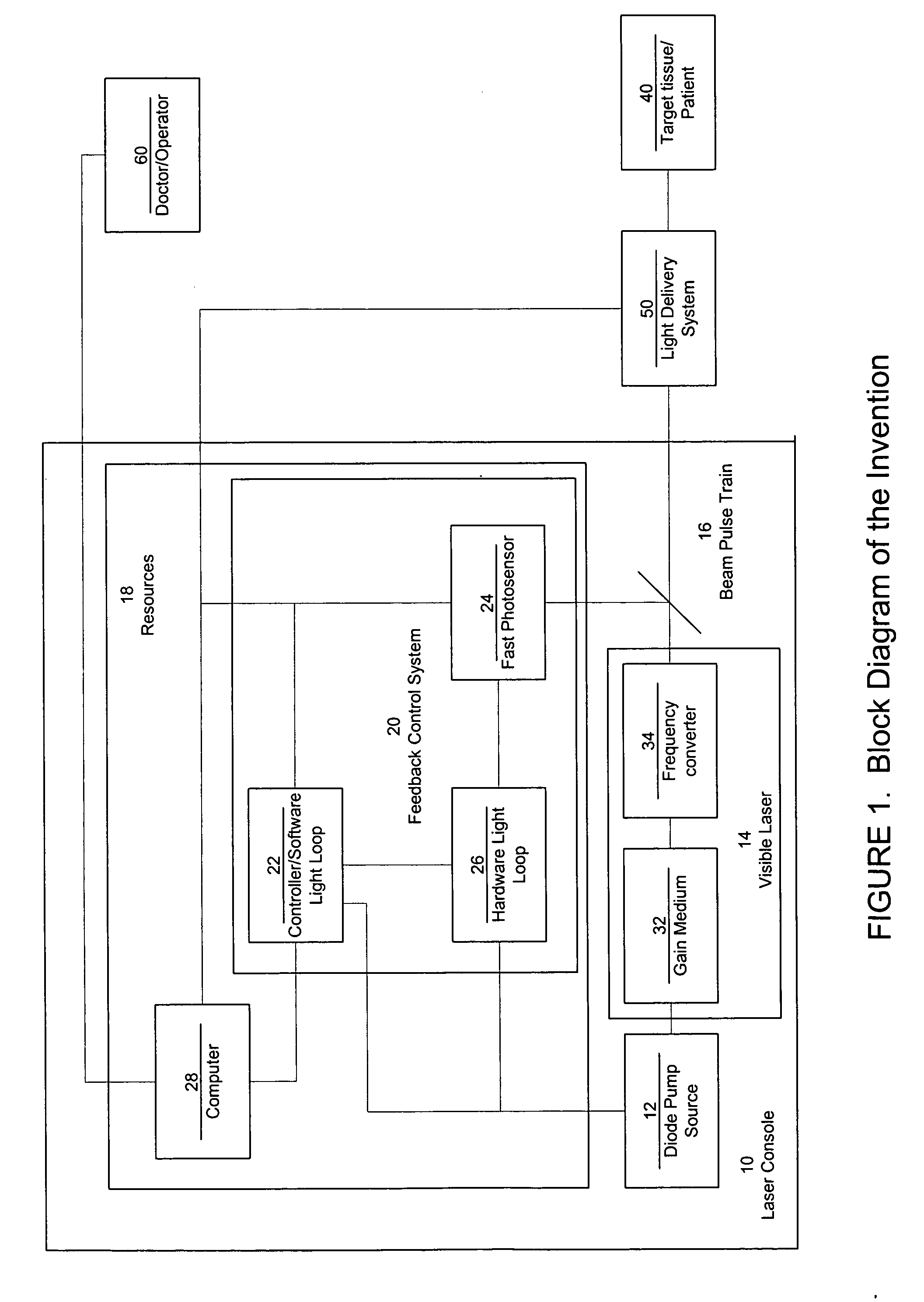
[0040] In this example, the resources 18 have a hardware light loop threshold set at 3 to 5% above the desired power level. At the start of each pulse, the requested light level is set to maximum and held there until the laser power reaches the desired level. This generates the fastest possible rise time. When the laser power reaches the desired level, the resources 18 hold the power just above the desired level. The resources 18 then ramps the requested power level down until the laser power is equal to or below the desired level. If it is equal to or below the desired level, it steps back up slowly. If it is above, it steps down slowly. The resources 18 make a new measurement before each decision to raise or lower the requested level.

[0041] At this point the resources 18 requested level is close to the proper level and the combination of hardware and software keep the light within 3 to 5% as long as the pulse is on. The end result is a very fast turn on and stable light level thr...

example 2

[0042] In this example, laser system 10 is utilized to treat RPE, capullochoris and choroids of the eye. Pulsed output 16 is directed to target site 40 of the eye and a temperature rise at the target site is non-additive from pulse to pulse. The target site 40 is an area of 50 microns to 3 mm. The pulsed output 16 has a wavelength range of 520 to 615 nm. The pulsed output 16 has a pulse on time of 25 microseconds to 10,000 microseconds, and a pulse off time of 750 to 10,000 microseconds.

example 3

[0043] In this example, laser system 10 is utilized to treat RPE, capullochoris and choroids of the eye. The pulsed output 16 is directed to a target site of the eye and a temperature rise at the target site is non-additive from pulse to pulse. The target site 40 is an area of 50 microns to 3 mm. The controller 22 has a high speed circuit that compares a signal from the photodetector 24, to a target power, and uses this comparison to determine the on and off time of each pulse. The signal from photodetector 24 is compared to a target power to determine the on and off times.

[0044] The pulsed output 16 has a wavelength range of 520 to 615 nm. The pulsed output 16 has a pulse on time of 25 microseconds to 10,000 microseconds, and a pulse off time of 750 to 10,000 microseconds.


PUM


Abstract

A laser system that includes a diode pump source. A frequency doubled solid state visible laser is pumped by the diode pump source and produces a pulsed laser output with a train of pulses. Resources provide instructions for the creation of the pulsed output, with on and off times that provide for substantial confinement of thermal effects at a target site. This laser system results in tissue specific photoactivation (or TSP) without photocoagulation damage to any of the adjacent tissues and without causing full thickness retinal damage and the associated vision loss.

Description

BACKGROUND OF THE INVENTION [0001] 1. Field of the Invention [0002] This invention relates generally to laser systems, and their methods of use, that produce short and controlled pulse width trains, and more particularly to frequency doubled, cw laser systems, and their methods of use, that produce visible pulse trains of the appropriate pulselength, duty factor, and power to perform ophthalmology treatments currently being performed in the near-infrared. [0003] 2. Description of the Related Art [0004] Laser photocoagulation (PC) is the current standard of care for the treatment of certain retinal diseases such as diabetic macular edema (DME), proliferative diabetic retinopathy (PDR), extrafoveal, juxtafoveal and some types of subfoveal retinal neovascularization (SRNV). The laser PC protocols validated by the diabetic retinopathy study (DRS), the early treatment of diabetic retinopathy study (ETDRS) and the macula photocoagulation study (MPS) all provide evidence for the beneficial...

Claims


Application Information

Patent Timeline
IPC IPC(8): H01S3/10H01S3/094H01S3/091
CPCA61B2018/00636A61F9/008A61F9/00821A61F2009/00844A61F2009/00863H01S3/094076H01S3/0941H01S3/1022H01S3/109H01S3/1305H01S3/1306H01S3/1312
Inventor TELFAIR, WILLIAMAVISA, RONALDMOHR, STUARTBUZAWA, DAVID M.
Owner IRIDEX CORP
Why Eureka
Try Eureka