Bridgeless boost converter with PFC circuit

a boost converter and circuit technology, applied in the direction of dc-dc conversion, conversion with intermediate conversion to dc, dc-dc conversion, etc., can solve the problems of increasing complexity of the input converter stage with power factor control, a great challenge for designers, and a great challenge in cost, reliability and ease of design, so as to achieve cost savings and efficiency gains

Inactive Publication Date: 2006-09-07
INTERNATIONAL RECTIFIER COEP
View PDF12 Cites 92 Cited by
  • Summary
  • Abstract
  • Description
  • Claims
  • Application Information

AI Technical Summary

Benefits of technology

[0036] Thanks to the innovation of new silicon technology as well as advanced integration and packaging technology, this input converter topology can now be implemented effortle

Problems solved by technology

However, finding a power management circuit solution that meets the criteria for full-scale efficiency and control poses a great challenge to designers in terms of costs, reliability and ease of design.
One element of increased complexity is the input converter stage with power factor control, required by new regulations in Europe and China.
However, these savings are hardly achievable without a broader adoption of variable speed compressor drives running either a standard AC induction or a BLDC compressor.
However, the adoption of electronic inverters for controlling the motor has generally not been enough to achieve these results.
These combined effects of poor power factor and harmonic disturbanc

Method used


Image

  • Bridgeless boost converter with PFC circuit
  • Bridgeless boost converter with PFC circuit
  • Bridgeless boost converter with PFC circuit

Examples


Embodiment Construction

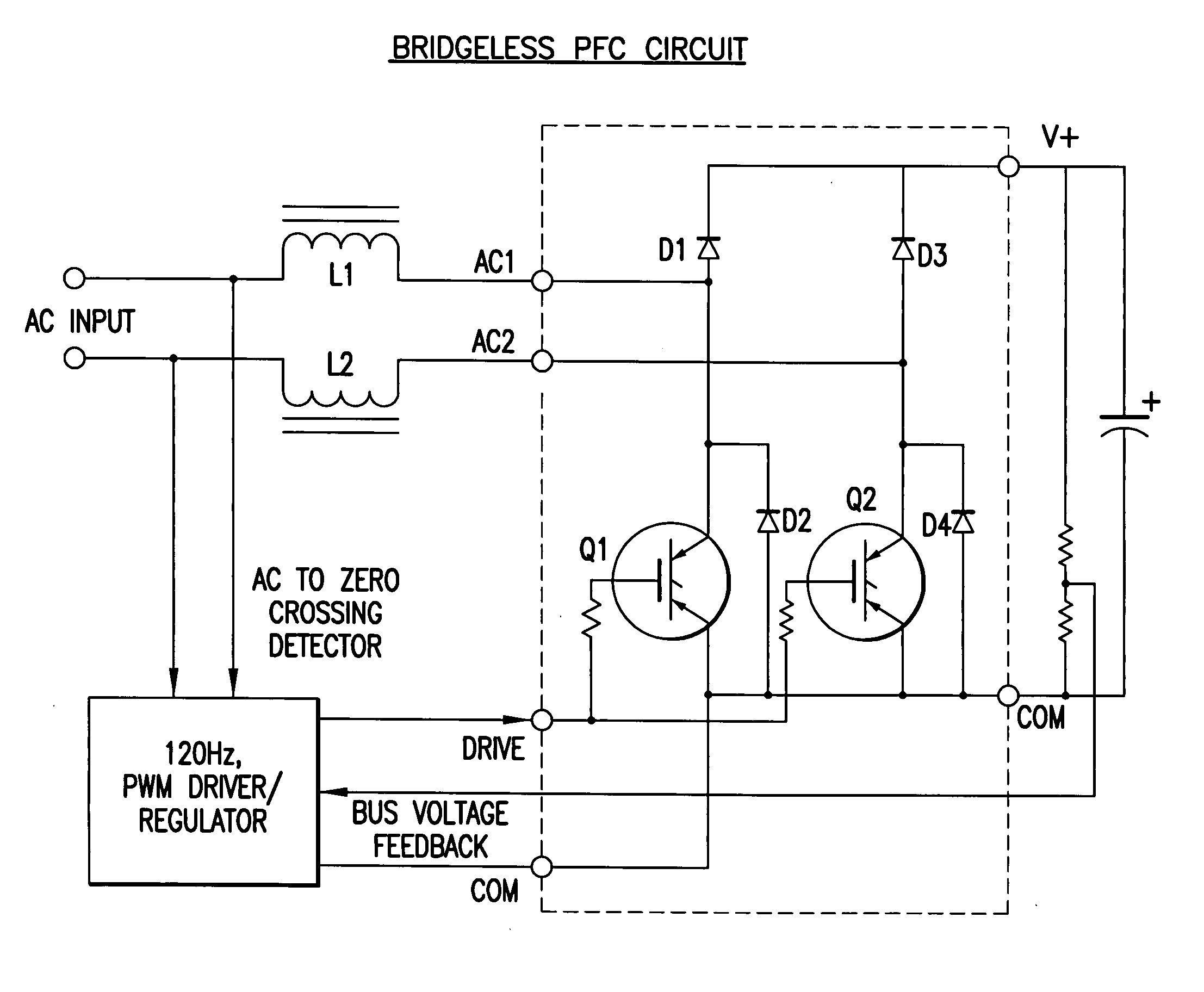
[0058] The circuit of FIG. 5 places the inductor(s) in the AC circuit, before the rectifier diodes D1-D4, so that D1 and D3 have the dual functions of rectification and boost diodes. It is apparent that the improved circuit has one less diode drop in the power flow. Since the circuit operates at 120 Hz, switching losses are virtually eliminated and D1-D4 and Q1-Q2 are standard speed components which have the added advantage of lower conduction losses than fast semiconductors. Q1 and Q2 may be IGBTs, for example.

[0059] The controller senses zero-voltage-crossing of the AC input signal and generates a PWM drive signal for the IGBT's Q1 and Q2.

[0060] The circuit delivers power factors of >0.99 without current sensing over typical line variations of + / − 10%. with efficiencies >98% in 230 VAC circuits delivering 1 KW at a DC bus voltage of 280 VDC.

[0061] The IGBT switches may be small (die size #2) since they conduct only on alternate half cycles even though they are driven simultaneo...


PUM


Abstract

A boost type power supply circuit for providing a DC output voltage comprising first and second semiconductor switches coupled between respective input lines and a common connection; an AC input voltage from an AC source being supplied across the input lines; first and second diodes coupled in series with respective ones of the switches; third and fourth diodes coupled across respective ones of the switches in a free-wheeling relationship with the switches; an inductance coupled in at least one of the input lines; a controller for controlling the conduction times of the switches by providing a pulse width control signal to each of the switches; wherein the controller turns on at least one of the switches during a positive half cycle of the AC voltage to allow energy storage in the inductance and turns off the at least one switch to allow the energy stored in the inductance to be supplied to an attached load through one of the first and second diodes and one of the third or fourth diodes; and the controller turns on at least one of the switches during a negative half cycle of the AC voltage to allow energy storage in the inductance and turns off at least one switch to allow the energy stored in the inductance to be supplied to the attached load through one of the first and second diodes and one of the third and fourth diodes. The controller determines an on-time and an off-time of a pulse of the pulse width modulated control signal during each half cycle of the AC voltage, the on-time and off-time of the pulse being controlled to regulate said output voltage and to provide power factor correction of said AC input voltage, based on either voltage sensing or current sensing.

Description

CROSS REFERENCE TO RELATED APPLICATIONS [0001] This application is based upon and claims priority of U.S. Provisional Ser. No. 60 / 666,950 filed Mar. 31, 2005 (IR-2965 PROV), incorporated by reference. [0002] This application is a continuation-in-part of U.S. Ser. No. 10 / 953,344 filed Sep. 29, 2004 (IR-2593), incorporated by reference, which is based upon and claims priority of U.S. Provisional Ser. No. 60 / 507,901 filed Oct. 1, 2003, also incorporated by reference.BACKGROUND OF THE INVENTION [0003] 1. Field of the Invention [0004] The present invention relates to a bridgeless boost converter with PFC circuit, and more particularly to a converter circuit usable, for example, in air-conditioning applications. [0005] 2. Related Art [0006] The increased demand for in-room air conditioning systems driven by environmental changes has started to affect energy consumption during the summer time in all industrialized and emerging countries. [0007] New government regulations and more energy-co...

Claims


Application Information

Patent Timeline
IPC IPC(8): H02M7/04H02M5/42
CPCH02M1/4233H02M7/219Y02B70/126Y02B70/10H02M1/0085H02M3/155
Inventor WOOD, PETER
Owner INTERNATIONAL RECTIFIER COEP
Why Eureka
Try Eureka