
Olefin Oligomerization

a technology of oligomerization and oligomerization, which is applied in the direction of hydrocarbon purification/separation, chemical/physical processes, and combustion gas purification/modification, etc., can solve the problems of additional components, complicated subsequent separation efforts, and more expensive and complicated fired heaters

Active Publication Date: 2006-09-07
EXXONMOBIL CHEM PAT INC
View PDF65 Cites 54 Cited by
  • Summary
  • Abstract
  • Description
  • Claims
  • Application Information

AI Technical Summary

Benefits of technology

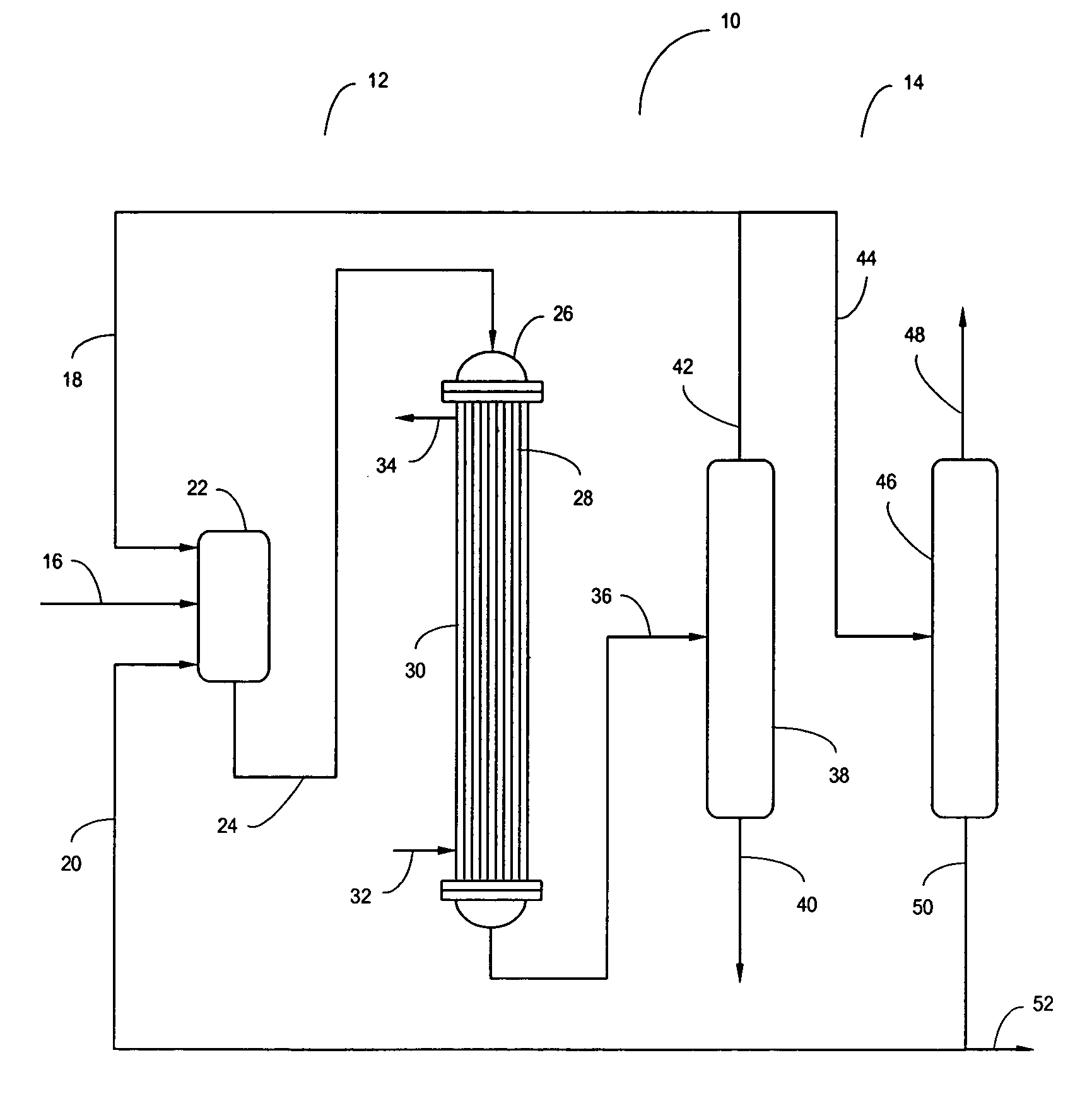
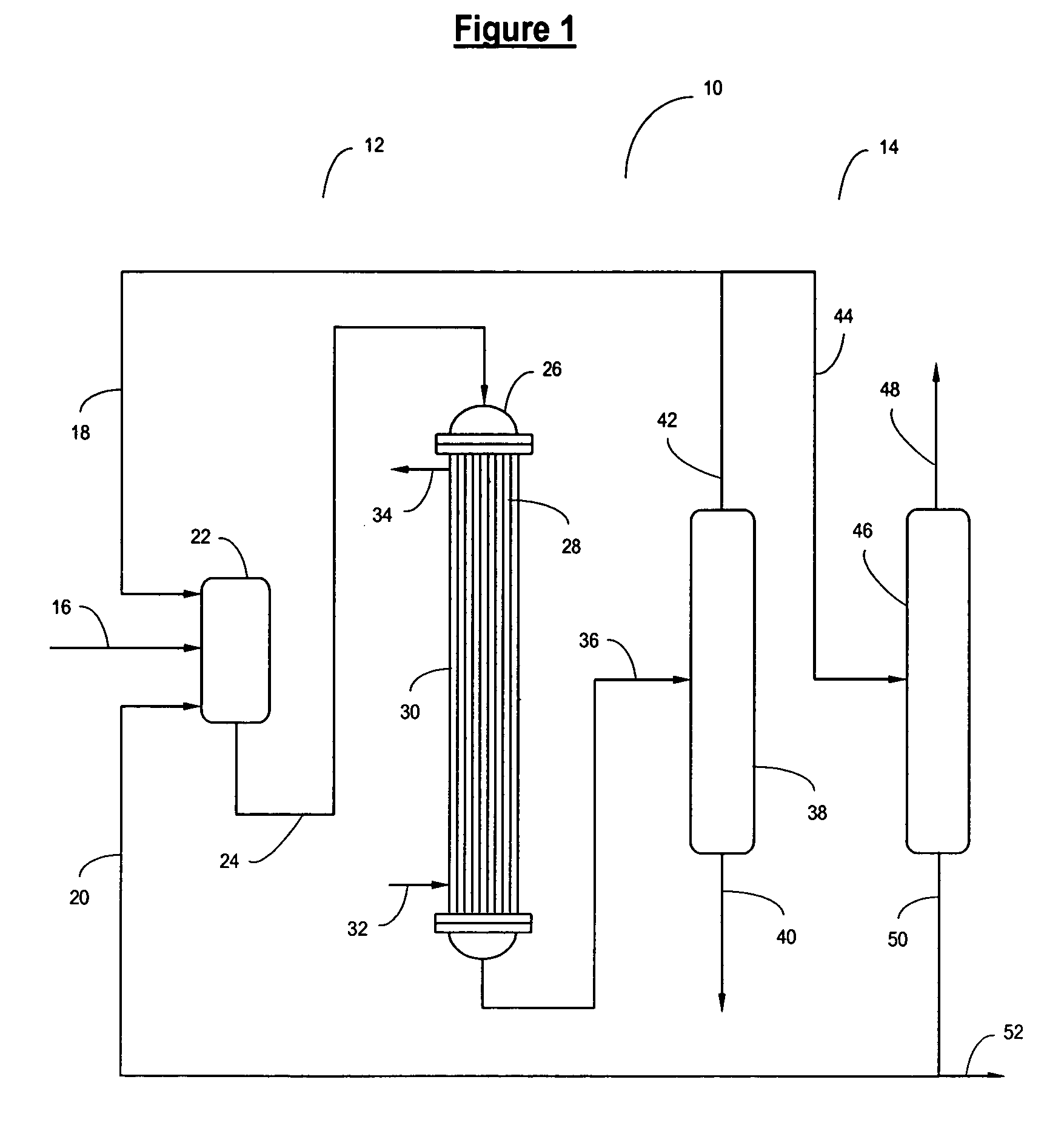
[0022] In one embodiment of the present invention, said first purge stream comprises from about 5 wt % to about 80 wt % of said light olefinic stream. In one embodiment of the present invention, said second purge stream is richer in C4− molecules than the first purge stream. In one embodiment of the present invention, said second purge stream comprises at least about 50 wt % C4− molecules. In one embodiment of the present invention, the second purge stream comprises at least about 50 wt % C4− saturates. In one embodiment of the present invention, the second purge stream comprises no greater than 30 wt % C5+ molecules. In one embodiment of the present invention, the second purge stream is in the vapor phase. In one embodiment of the present invention, said second olefinic stream is richer in C5-C8 molecules than the first purge stream. In one embodiment of the present invention, the second olefinic stream comprises at least about 50 wt % C5-C8 molecules. In one embodiment of the present invention, the second olefinic stream comprises at least abo

Problems solved by technology

Further, a high molecular weight oligomer product requires very high temperatures for the fractionation tower bottoms streams that may eliminate the use of simple steam reboilers and require more expensive and complicated fired heaters.
The recycle streams in conventional olefin oligomerization processes are produced in a variety of rather complicated fashions with numerous unit operations, typically including some sort of single stage flash drum providing a very crude separation of reactor product as a means of providing some of the relatively heavy components, followed by various fractionation schemes which may or may not provide sharper separations, and again often providing heavy components as recycle.
These additional components further complicate subsequent separation efforts, for example, the addition of hydrogen as disclosed in U.S. Pat. No. 4,544,792 (and in U.S. Pat. No. 4,879,428 noted above, among others).

Method used


Image

  • Olefin Oligomerization
  • Olefin Oligomerization

Examples


example 1

[0088] Olefinic feedstock and recycle materials were prepared as shown in Table 1 and were oligomerized over a catalyst comprising 65 wt % of 0.02 to 0.05 micron crystals of ZSM-5 having a SiO2 / Al2O3 molar ratio of 50:1, and 35 wt % of an alumina binder. The catalyst was in the form of 1 / 16 inch extrudates and about 90 cc of catalyst was blended with about 202 cc of inert, silicon carbide beads to reduce the heat generation per unit volume of reaction and placed in the reaction bed of a tubular reactor equipped with a heat management system that allowed the oligomerization reaction to proceed under near isothermal conditions.

TABLE 1Charge ACharge BFeedRecycleFeedRecycleWt. %49.5250.4841.8458.16ProportionComp. Wt. %11.0211.39Ethane0.000.000.000.00Ethylene0.000.000.000.00Propane0.000.000.010.00Propene0.000.000.000.00iso-butane7.240.100.990.02n-butane0.080.0011.610.03t-butene-20.000.1027.170.03butene-172.280.0016.310.00iso-butene2.880.002.650.01c-butene-20.010.0020.140.00iso-pentane0...

example 2

[0090] The same apparatus and procedure as Example 1 was utilized for a second, extended experimental run with a fresh batch of catalyst and another set of charge compositions as shown in Table 3. The olefinic feedstocks shown in Table 3 were produced by reacting methanol over a SAPO-34 catalyst generally according to the method of U.S. Pat. 6,673,978, with separation of the methanol reaction products to provide a C4+ olefin composition. Over 90 wt % of the olefins in each feed composition were normal in atomic configuration, and the feed composition further contained about 1000 wppm oxygenates, such as methanol and acetone (not shown in Table 3), and 1000 ppm dienes. Some minor adjustments of some components in the feed compositions were made by additions of reagent grade materials to test certain aspects of the operation.

[0091] The olefinic recycle compositions shown in Table 3 were produced by taking accumulated batches of the reaction products from the first and this second exp...

example 3

[0093] Several batches of distillate materials were produced from the fractionation of various batches of reactor product obtained in the first and second experimental runs. The carbon number distribution of those distillate material batches, via the Linear Paraffin GC method, are provided in Table 5. Distillates 1 and 2 in Table 5 were obtained from fractionation operations using the aggregate reactor product from the first experimental run, while Distillate 3 was obtained from fractionation operations of the aggregate reactor product from Charges C, D, and E of the second experimental run. All of the distillate materials contain all of the C11+ and almost all of the C10 material present from the reaction products, i.e., no separation of any components heavier than C11 was conducted on the reactor product in obtaining the distillate materials. As obtained directly from the reactor product via the fractionation tower, all the distillate materials are over 90 wt % non-normal olefin, ...


PUM

PropertyMeasurementUnit
Temperatureaaaaaaaaaa

Abstract

A process for producing a hydrocarbon composition that comprises contacting a feed stream, that comprises at least one C3 to C8 olefin, and an olefinic recycle stream, that comprises a first olefinic recycle stream and no more than 10 wt % of C10+ non-normal olefins, with a molecular sieve catalyst in a reaction zone under olefin oligomerization conditions producing an oligomerization effluent stream; separating the oligomerization effluent stream to produce a first olefinic stream, that has a weight ratio of C4− / (C5-C8) molecules from about 0.8 to about 1.2 times the weight ratio of C4− / (C5-C8) molecules found in the oligomerization effluent stream, and a first hydrocarbon product stream, that comprises at least 1 wt % and no more than 30 wt % of C9 non-normal olefin; and splitting the first olefinic stream to produce the first olefinic recycle stream and a first purge stream.

Description

CROSS REFERENCE TO RELATED APPLICATIONS [0001] This application claims the benefit of U.S. Provisional Application 60 / 648,947, filed Jan. 31, 2005; U.S. Provisional Application No. 60 / 648,938, filed Jan. 31, 2005; and U.S. Provisional Application No. 60 / 727,563, filed Oct. 17, 2005, all of which are fully incorporated herein by reference. The present application is related by subject matter to co-pending U.S. Patent Application Serial No. AWAITED, filed Jan. 27, 2006 (Atty. Docket No. 2005B011A); U.S. Patent Application Serial No. AWAITED, filed Jan. 27, 2006 (Atty. Docket No. 2005B011B); U.S. Patent Application Serial No. AWAITED, filed Jan. 27, 2006 (Atty. Docket No. 2005B011D); and U.S. Patent Application Serial No. AWAITED, filed Jan. 27, 2006 (Atty. Docket No. 2005B011E).FIELD OF THE INVENTION [0002] This invention relates to an olefin oligomerization process for producing hydrocarbon compositions useful as fuels, such as jet fuel and diesel fuel. BACKGROUND OF THE INVENTION [0...

Claims


Application Information

Patent Timeline
IPC IPC(8): C07C2/02
CPCC07C2/12C10G50/00C07C11/02
Inventor KUECHLER, KEITH H.BROWN, STEPHEN HAROLDVERBERCKMOES, AN AMANDINEPUTTEMANS, MARC P.SILVERBERG, STEVEN E.
Owner EXXONMOBIL CHEM PAT INC
Learn More