Detecting gas in fluids

a technology of fluids and gas, applied in the direction of material analysis, optical radiation measurement, instruments, etc., can solve the problems of change in the resistance of the sensor, the physical sensor itself reacting with the gas/air mixture flowing by, and several problems, so as to achieve strong response, strong response, and the effect of not deteriorating the consistency and repeatability of the sensor

Inactive Publication Date: 2006-09-14
VARCO I P INC
View PDF26 Cites 66 Cited by
  • Summary
  • Abstract
  • Description
  • Claims
  • Application Information

AI Technical Summary

Benefits of technology

[0018] In one particular aspect, a gas detection system according to the present invention has a methane sensor and a propane sensor, each of which is connected to a corresponding gas chamber interface board (GCIB). The GCIB's provide an interface between the sensors and a drive for an infra-red lamp (one lamp in each sensor); and each GCIB performs amplification and signal conditioning on the sensor output signals and does an analog-to-digital (A / D) conversion of data from the sensors. By doing this on the GCIB's, susceptibility to noise is reduced. The sensors are calibrated on the basis of the digitized signals (digitized signals produced by the GCIB's), thus the calibration can be handled completely in software.
[0020] Systems according to the present invention can measure levels of hydrocarbons (e.g. methane, ethane, propane, butane, and iso-butane). In one aspect, the sensors are calibrated for 0 to 100% volume of gas in air of methane and propane, however both sensors are sensitive at some level to other hydrocarbons. The sensors in such an embodiment do not completely isolate methane and propane from other hydrocarbons, but rather, the methane sensor provides a stronger response to methane and ethane (see, e.g. curve C1+C2, FIG. 6) and the propane sensor provides a stronger response to propane, butane, and iso-butane (see, e.g. curve C3+C4+C5, FIG. 6). Systems according to the present invention can be portable with an easily emplaceable lightweight-polyurethane-encased gas trap, in one aspect with a gas dryer; a component-specific infra-red gas detector system, a laptop computer, and a wireless modem. In one particular aspect, using a wireless modem or similar device, a wireless portable gas monitor is provided.

Problems solved by technology

Heat or power dissipation results in a change in the resistance of the sensor.
The most inherent disadvantage is that the physical sensor itself reacts with the gas / air mixture flowing by it.
This allows several problems to occur.
The reaction of the sensor to gas can deteriorate the sensor over time and eventually the sensor's sensitivity and repeatability cannot be duplicated.
Consistency can be lost on long wells or when units are in the field for long periods of time.
Moisture in the gas / air sample can corrode or react with the physical sensor reducing the sensors sensitivity and lifespan.
H2S, N2 and CO2 can cause sensors to react giving false gas indications, going negative and poisoning the sensor until sensitivity is lost.
Any coatings applied on top of the physical surface of the sensor can reduce the sensor's sensitivity.
Many prior art sensors which are sensitive-specific to methane (C1) alone do not work as a total gas detector.
Some of these sensors never show any indication when zones rich in heavy hydrocarbons are drilled.

Method used


Image

  • Detecting gas in fluids
  • Detecting gas in fluids
  • Detecting gas in fluids

Examples


Embodiment Construction

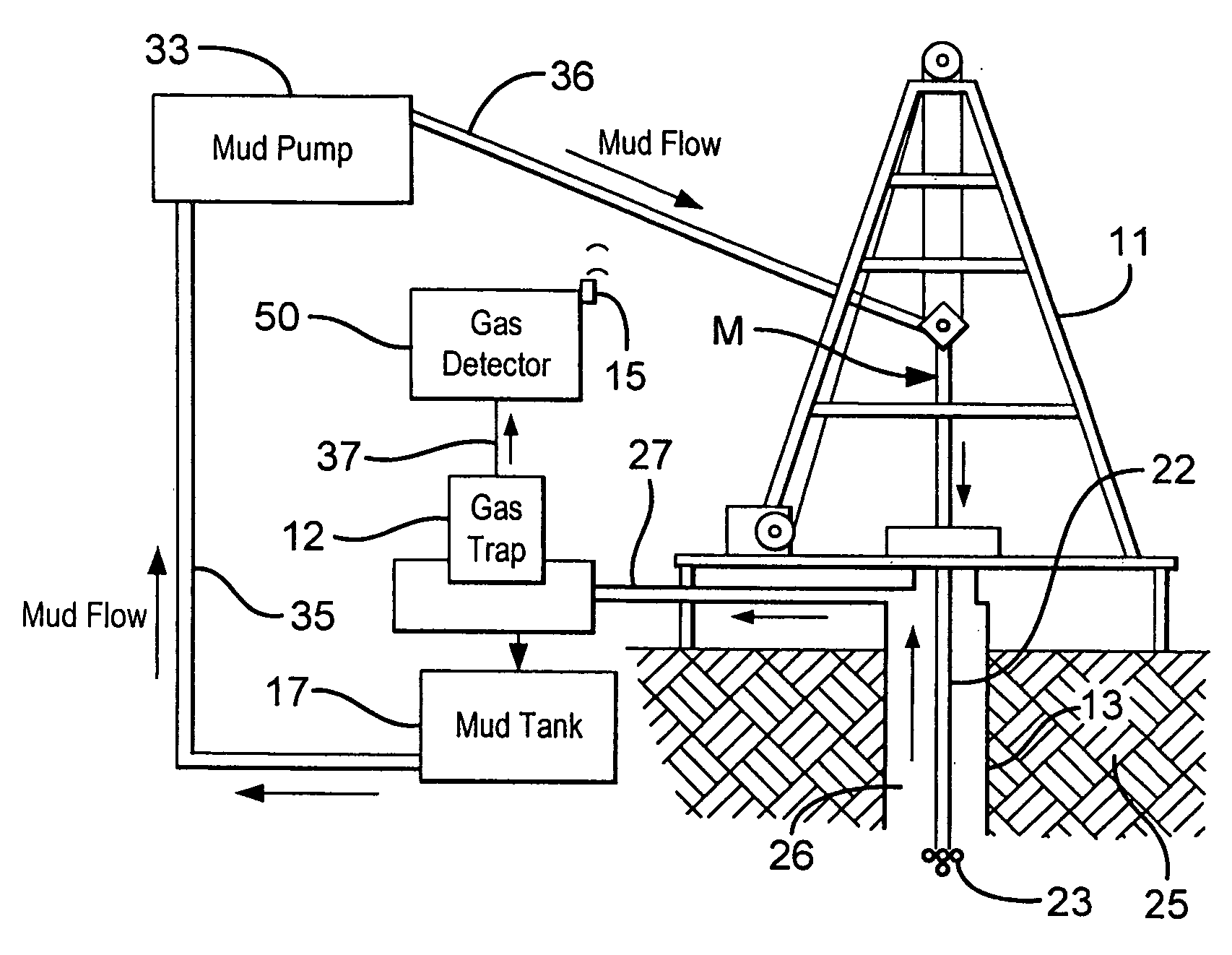
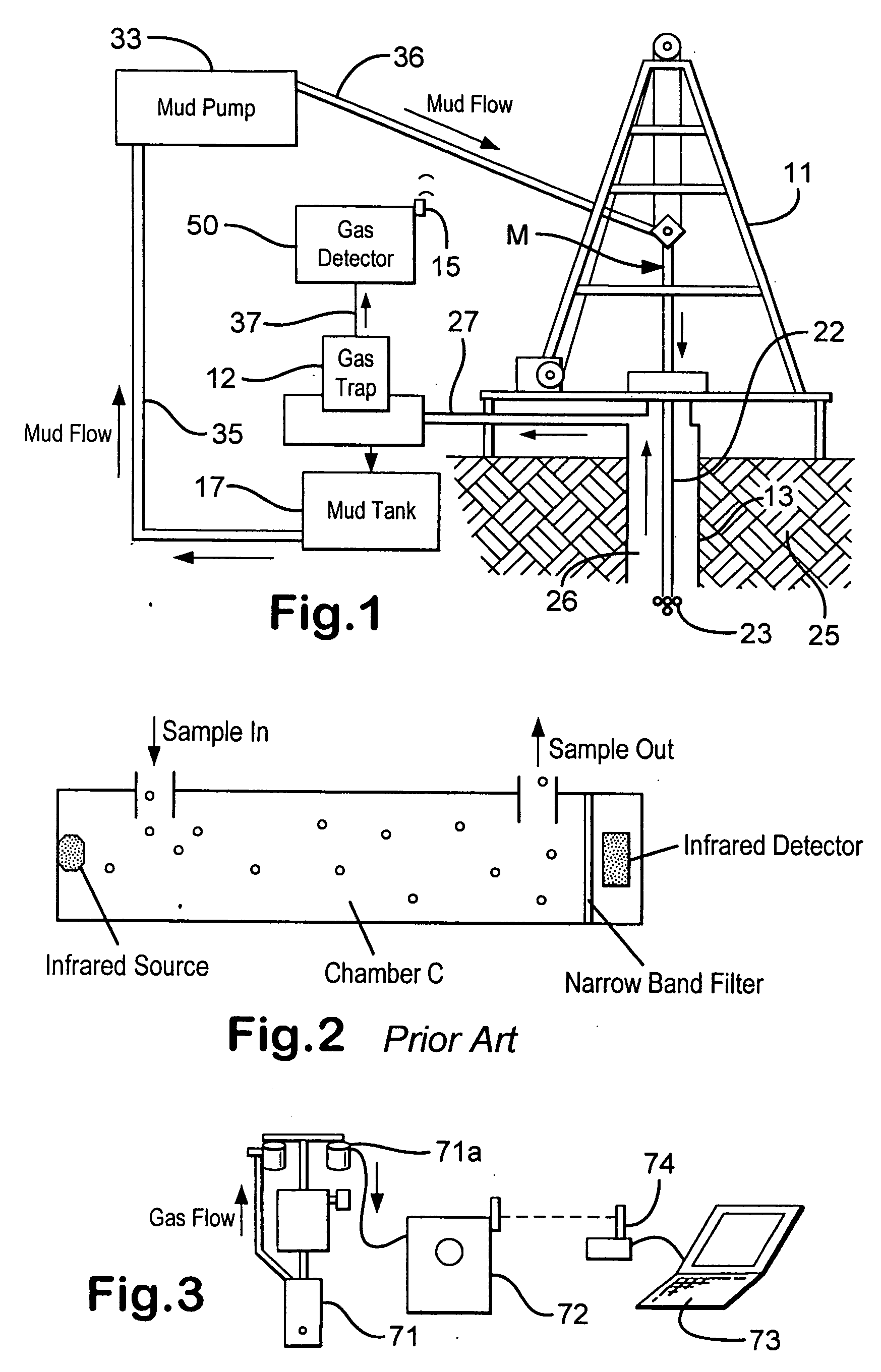
[0033] As shown in FIG. 1 a gas detector 50 according to the present invention receives gas samples in a polyflow line 37 from a gas trap 12. A drilling rig 11 drills a well 13 into a formation 25. A mud pump 33 pumps mud M in a line 36 into the well 13 down a drillstring 22, to and through a bit apparatus 23, and then up in an annulus 26 to an exit line 27 which feeds into the gas trap 12. The mud M exits the gas trap 12 and flows into a mud tank17 from which the mud pump 33 pumps the mud in a line 35 back to the line 36. A transmitter or modem 15 (e.g. wireless or hardwired) transmits signals from the gas detector 50 to apparatus or systems such as a computer, computer system, network, or a data acquisition system or apparatus.

[0034]FIG. 2 shows a typical prior art infra-red sensor system in which infra-red light from an infra-red source passes through material to be analyzed in a chamber C, then through a narrow band filter, to an infra-red detector. The material flows into the ...


PUM


Abstract

A method for detecting gas in a fluid, the system including flowing fluid bearing gas through a gas trap apparatus, flowing gas trapped by the gas trap apparatus to and through an infra-red gas detection system for detecting the gas, the infrared gas detection system having apparatus for isolating absorption spectra of the gas, producing with the infra-red gas detection system analog signals indicative of levels of the gas, transmitting the analog signals to a first processor for converting the analog signals to digital signals, transmitting the digital signals from the first processor to a second processor, producing with the second processor digital signals indicative of the level of the gas.

Description

BACKGROUND OF THE INVENTION [0001] 1. Field Of The Invention [0002] The present invention is directed to detecting gas in fluids, e.g. drilling fluid that has been circulated through a wellbore and, in one particular aspect, to systems and methods for detecting individual hydrocarbons, e.g., but not limited to, methane and propane, with infrared sensing apparatus. [0003] 2. Description of Related Art [0004] The prior art discloses a wide variety of systems and methods for detecting gas in drilling fluid or “mud” that is circulated down a drillstring, through a bit, and then back out of a wellbore during drilling. During a drilling operation, the mud is continuously pumped down through the drill string and into the region around the drill bit and then back up a borehole annulus to the surface. Often the mud is made up of clays, chemical additives and an oil or water base and performs several important functions. The mud cools and lubricates the drill bit, carries drill cuttings back ...

Claims


Application Information

Patent Timeline
Patent Type & Authority Applications(United States)
IPC IPC(8): G01J5/02A47J43/044A47J43/07
CPCG01N21/3504E21B21/01
Inventor GUNN, SCOTT EDWINDEBLIEK, JOHN WESLEY
Owner VARCO I P INC
Why Eureka
Try Eureka