Polarization-optimized illumination system

a technology of illumination system and polarization, applied in the field of illumination system, can solve the problems of poor light transmission efficiency, poor imaging performance, integrator rods, etc., and achieve the effect of high efficiency

Inactive Publication Date: 2006-09-14
CARL ZEISS SMT GMBH
View PDF33 Cites 32 Cited by
  • Summary
  • Abstract
  • Description
  • Claims
  • Application Information

AI Technical Summary

Benefits of technology

[0012] Among the objects of the present invention are to create an illumination system that is suitable, in particular, for use in a microlithographic projection exposure machine and which transmits the light from an assigned light source with high efficiency, has a negligible influence on the angular distribution of the penetrating light, and permits a defined setting of the state of polarization of the emerging light.

Problems solved by technology

Any variation in the angular spectrum that is introduced in the light path between the conjugate pupil planes leads to a distortion of the intensity distribution present in the objective pupil, and this can lead in the case of dipole or quadrupole illumination, for example, to an asymmetric irradiation in the case of the imaging two-beam interference, and thus to a worsening of the imaging performance.
This is opposed, as a disadvantage, by an efficiency of light transmission that is worse by comparison with integrator rods, since the passing surface has non-transmitting dead areas in the region of boundary surfaces between the individual lenses.
A disadvantage of integrator rods is their only poorly controllable influence on the state of polarization of the penetrating light.
Firstly, use is made of an optical path of great length.
Secondly, there are many skew (total) reflections at the sides which, owing to their phase-shifting effect, vary the state of polarization of the penetrating light uncontrollably.

Method used


Image

  • Polarization-optimized illumination system
  • Polarization-optimized illumination system
  • Polarization-optimized illumination system

Examples


Embodiment Construction

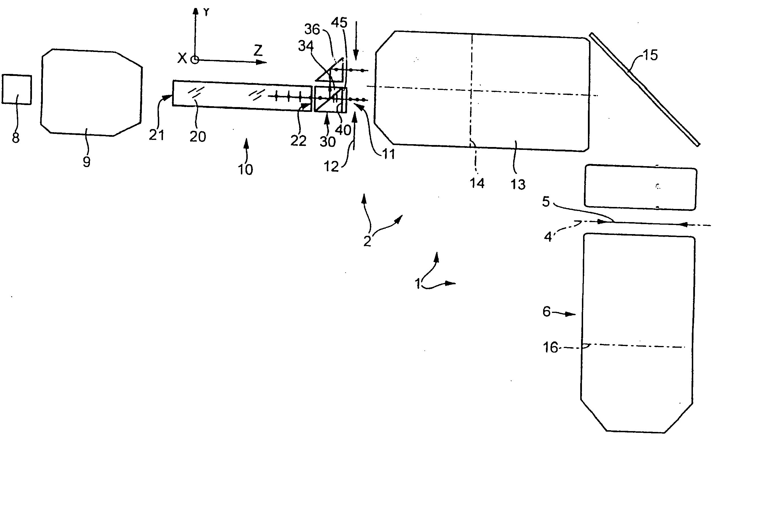
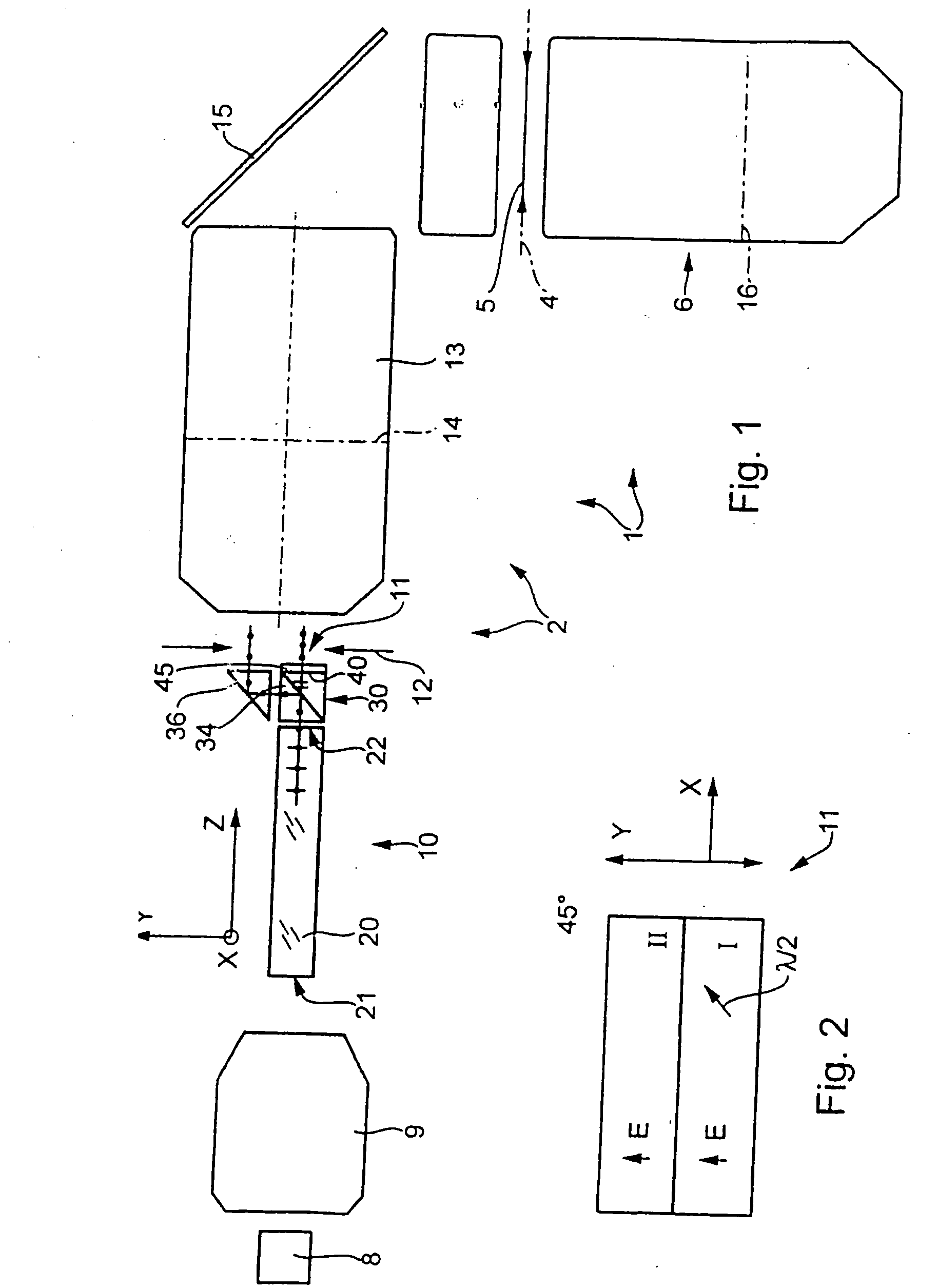
[0054] An example of a projection exposure machine 1 for the microlithographic production of integrated circuits and other finely structured components in conjunction with resolutions down to fractions of 1 μm is provided in FIG. 1. The machine 1 comprises an illumination system 2 for illuminating a photomask 5 arranged in the image plane 4 of the illumination system, and a projection objective 6 that images the pattern, arranged in its object plane 4, of the photomask into the image plane 7 of the projection objective on a reducing scale. A semiconductor wafer coated with a photosensitive layer, for example, is located in the image plane 7.

[0055] Serving as light source of the illumination system 2 is a laser 8, for example an excimer laser customary in the deep ultraviolet (DUV) region and having an operating wavelength of 248 nm, 193 nm or 157 nm. The light of the output light beam is largely linearly polarized. A downstream optical device 9 shapes the light from the light sourc...


PUM

PropertyMeasurementUnit
operating wavelengthaaaaaaaaaa

Abstract

An illumination system for a projection exposure machine, operating with ultraviolet light, for microlithography has an angle-conserving light mixing device with at least one integrator rod that has an entrance surface for receiving light from a light source, and an exit surface for outputting exit light mixed by the integrator rod. At least one prism arrangement for receiving exit light and for varying the state of polarization of the exit light is placed downstream of the integrator rod. A preferred prism arrangement has a polarization splitter surface, aligned transversely to the direction of propagation of the exit light, which passes light fractions with p-polarization without hindrance, and reflects fractions with s-polarization. The separated beams with orthogonal polarization are parallelized by means of a reflecting surface aligned parallel to the polarization splitter surface, and the same state of polarization is set for both partial beams by means of a suitable retarder.

Description

CROSS-REFERENCE TO RELATED APPLICATIONS [0001] This is a continuation of application Ser. No. 10 / 913,575 filed on Aug. 9, 2004, which is a continuation of International Application PCT / EP03 / 01146, filed on Feb. 5, 2003, which was published under PCT Article 21(2) in German, the entire disclosures of which are hereby incorporated by reference.BACKGROUND OF THE INVENTION [0002] 1. Field of Invention [0003] The invention relates to an illumination system for an optical device, in particular for a projection exposure machine for microlithography, and to a projection exposure machine equipped with such an illumination system. [0004] 2. Description of the Related Art [0005] The performance of projection exposure machines for the microlithographic production of semiconductor components and other finely structured components is substantially determined by the imaging properties of the projection optics. Moreover, the image quality and the wafer throughput achievable with a machine are also ...

Claims


Application Information

Patent Timeline
Patent Type & Authority Applications(United States)
IPC IPC(8): G02B27/28G02B5/30G03F7/20
CPCG02B27/283G03F7/70075G03F7/70566G03F7/70958
Inventor SCHUSTER, KARL-HEINZ
Owner CARL ZEISS SMT GMBH
Why Eureka
Try Eureka