
Optical information recording medium, method for reproducing optical information recording medium, and optical information processing apparatus using optical information recording medium

Inactive Publication Date: 2006-09-14
SHARP KK
View PDF6 Cites 17 Cited by
  • Summary
  • Abstract
  • Description
  • Claims
  • Application Information

AI Technical Summary

Benefits of technology

[0030] The present invention is made in view of the need in the high density recording / reproduction, and its object is to provide (i) an optical information recording medium which stores information in density higher than the resolution limit of the reproduction optical system, but which allows the information to be precisely and securely reproduced; and (ii) a method for reproducing the optical information recording medium.

Problems solved by technology

However, this causes decrease of intensity of a signal generated from a fine recording pit, with the result that influence of noise becomes great.
However, each of the techniques disclosed in Patent documents 1 through 3 suffers from the following problems.
Therefore, the mask layer provided in the optical information recording medium exhibits the mask effect when being melted by increasing the temperature of the mask layer to the certain temperature or greater; however, as the optical information recording medium is recorded and / or reproduced over and over, the composition and the shape of the mask layer are so changed that the mask effect is gradually deteriorated.
Specifically, substantially no mask effect is exhibited after recording and / or reproducing the optical information recording medium several thousand times. For this reason, the optical information recording medium described in Patent document 1 is insufficient in terms of durability, stability, and reliability.
However, the chemical structure of each of such organic materials is also changed by absorption of heat, so that the organic materials are defective in terms of thermal stability.
Therefore, as the recording and / or reproduction are carried out over and over, the mask layer is so deteriorated that the mask effect is gradually deteriorated.
Specifically, substantially no mask effect is exhibited after carrying out recording and / or reproduction several thousand times. In other words, such durability for the repeated recording / reproduction is unpractical.
Thus, as is the case with Patent document 1, the optical information recording medium having such a mask layer is insufficient in terms of the durability, stability, and reliability.
As such, each of the materials exemplified above is defective in terms of the thermal stability, and does not have practical durability for the repeated recording / reproduction.
However, the following general problems arise in adopting each of the above materials as the nonlinear optical material: (1) highly pure and large crystals are required; (2) it is difficult to carry out crystal uniformity control upon film formation; (3) acceptability is low in a crystal orientation angle or the like; (4) strong light intensity is required for the attainment of the nonlinear optical property; (5) optical damage resistance is low; and the like.
Such a film forming method actually makes it difficult to solve the aforementioned problems.
That is, the nonlinear optical material is thus mixed with the film forming materials, so that it is difficult to obtain highly pure and large crystals of the nonlinear optical material, or to secure uniformity of the crystals thereof.
This makes it difficult to obtain (i) stable growth of the crystals, and (ii) preferred crystal orientation.
Moreover, the film forming method makes it difficult to carry out the grain diameter control.
However, this optical information recording medium is weak in terms of the optical damage resistance, and therefore suffers from problems of reproduction stability and durability.
As described above, it is difficult to control the property of each material for use in the optical information recording medium described in Patent document 2.
Moreover, the materials therefor are limited, so that freedom in medium designing is low.
This is not practical.
In cases where irradiation of such light is carried out over and over for the recording / reproduction, the entire medium including the substrate and the thin film are likely to be deteriorated.
Therefore, the optical disk suffers from problems in reproduction stability and durability.
This makes it difficult to carry out the property control in the optical disk described in Patent document 3, and to carry out the medium designing thereof, and to achieve implementation thereof.

Method used


Image

  • Optical information recording medium, method for reproducing optical information recording medium, and optical information processing apparatus using optical information recording medium
  • Optical information recording medium, method for reproducing optical information recording medium, and optical information processing apparatus using optical information recording medium
  • Optical information recording medium, method for reproducing optical information recording medium, and optical information processing apparatus using optical information recording medium

Examples


embodiment 1

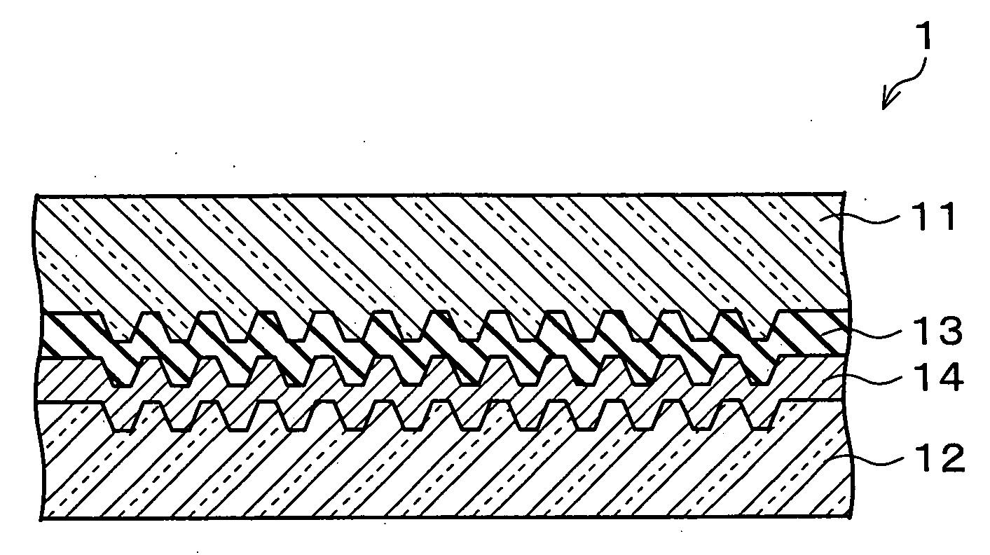
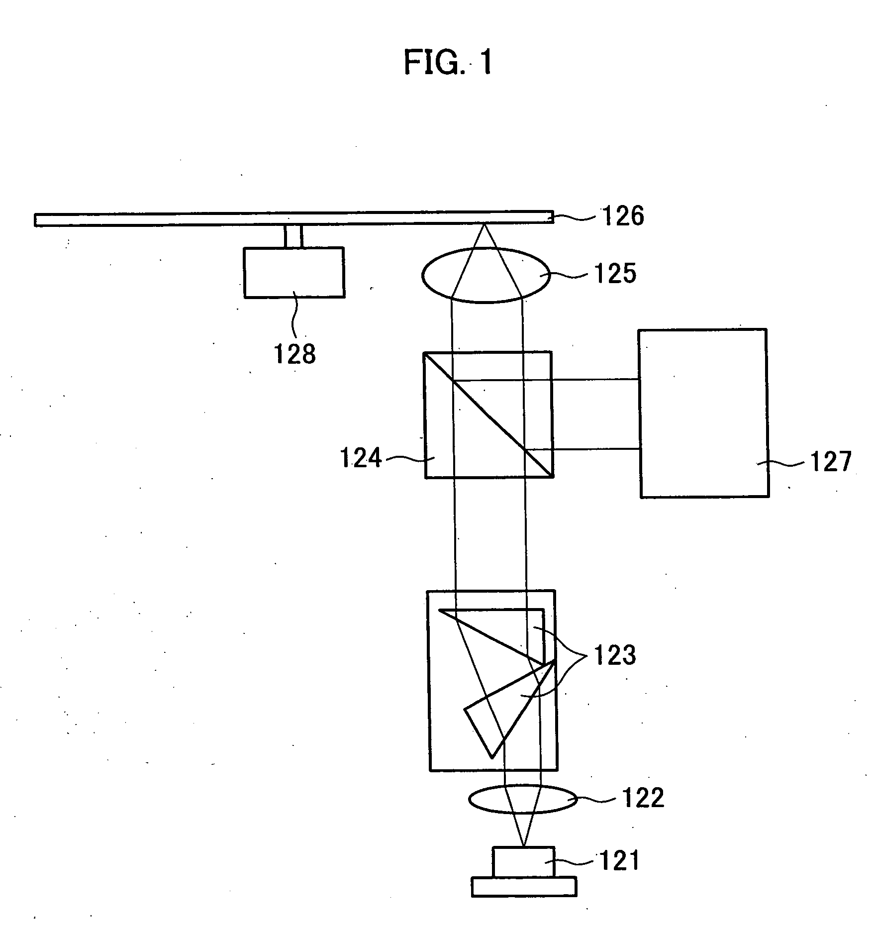
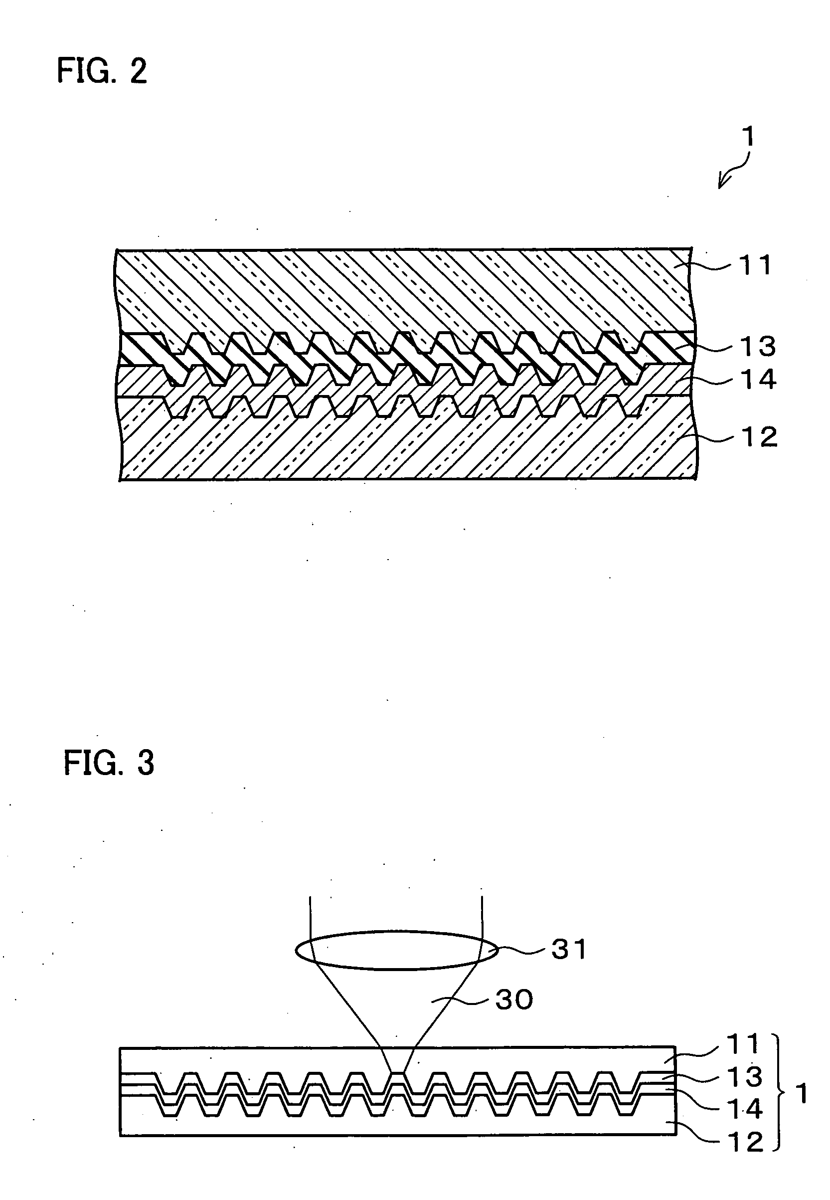
[0077] One embodiment of an optical information recording medium of the present invention will be described below with reference to FIG. 1 through FIG. 17.

[0078] Firstly explained is a major structure of a recording / reproducing apparatus (optical information processing apparatus) which can record information onto the optical information recording medium and which can reproduce information therefrom.

[0079] The recording / reproducing apparatus includes a laser light source, light collection optical means, relative movement means, photoelectric conversion means, servo means, address information detection means, reproduction signal demodulation circuit, and the like.

[0080] A specific example of the laser light source is a semiconductor laser emitting light whose wavelength is 405 nm; or the like.

[0081] The light collection optical means collects, on the optical information recording medium, laser light (laser beam) emitted from the laser apparatus. The light collection optical means ...

embodiment 2

[0198] Another embodiment of the present invention will be explained below. For ease of explanation, materials having the equivalent functions as those shown in the drawings pertaining to Embodiment 1 will be given the same reference symbols, and explanation thereof will be omitted here.

[0199] Firstly explained is a structure of an optical information recording medium of the present embodiment. See FIG. 15 illustrating the structure of the present embodiment.

[0200] As shown in FIG. 15, the optical information recording medium 2 has a structure obtained by providing a light absorbing film 15 in the optical information recording medium 1 of Embodiment 1 instead of the reflecting film 14. Note that, a reproduction method thereof, a manufacturing method thereof, an evaluation apparatus used herein, and an evaluation method used herein are the same as those in Embodiment 1, respectively.

[0201] Unlike the reflecting film 14, the light absorbing film 15 is not made of a metal having a h...

embodiment 3

[0215] Still another embodiment of the present invention will be explained below with reference to FIG. 18 and FIG. 19. For ease of explanation, materials having the equivalent functions as those shown in the drawings pertaining to Embodiment 1 will be given the same reference symbols, and explanation thereof will be omitted here.

[0216] An optical information recording medium according to the present embodiment is a readable / recordable (either write-once-read-many or re-writable) optical information recording medium 3 as shown in FIG. 18 and FIG. 19. Provided in the optical information recording medium 3 are a transparent resin layer 11, a super resolution reproducing film 13, a recording layer 16, and a substrate 12 in this order from the side via which a recording / reproduction beam 32 enters. The recording / reproduction beam 32 is a light beam for use in recording and reproduction. The super resolution reproducing film 13 is the same as that of Embodiment 1.

[0217] The recording l...


PUM


Abstract

In order to realize (A) an optical information recording medium in which information is stored in high density and can be precisely and securely reproduced, (B) a method for reproducing the optical information recording medium, and (C) an optical information processing apparatus using the optical information recording medium, an optical information recording medium 1, 2, or 3 of the present invention includes: (a) a substrate 12, having pits and / or grooves, each of which is made up of a rise and a recess, and each of which corresponds to recorded information that is optically reproduced by irradiation of a light beam; and (b) at lease one super resolution reproducing film 13, which has an optical property to be changed in response to a temperature increase caused by the irradiation of the light beam, the optical property of the super resolution reproducing film being reversibly changed depending on a temperature change in the super resolution reproducing film. The optical information recording medium 3 of the present invention further includes a recording layer.

Description

[0001] This Nonprovisional application claims priority under 35 U.S.C. § 119(a) on patent application Ser. No. 2005 / 59698 filed in Japan on Mar. 3, 2005, and patent application Ser. No. 2006 / 45848 filed in Japan on Feb. 22, 2006, the entire contents of which are hereby incorporated by reference.FIELD OF THE INVENTION [0002] The present invention relates to an optical information recording medium, a method for reproducing the optical information recording medium, and an optical information processing apparatus using the optical information recording medium. More specifically, the present invention relates to, e.g., (i) an optical information recording medium from which information is either optically reproduced or optically recorded by way of a light beam such as a laser beam, and whose recording density is improved by providing a layer whose optical property changes depending on temperature; (ii) a method for reproducing the optical information recording medium; and (iii) an optical...

Claims


Application Information

Patent Timeline
IPC IPC(8): G11B7/24G11B7/2405G11B7/24062G11B7/24065
CPCB82Y10/00G11B7/24G11B7/243G11B2007/24304G11B2007/2432
Inventor MORI, GOTAJIMA, HIDEHARUTAKAMORI, NOBUYUKIYAMAMOTO, MASAKIHARADA, YASUHIRO
Owner SHARP KK
Learn More