Semiconductor integrated circuit device and its manufacturing method
a technology of integrated circuit and semiconductor, applied in the direction of semiconductor devices, electrical appliances, transistors, etc., can solve the problems of deterioration of access speed, inability to design a large read current for each conventional cell, and several problems of foregoing memory cells, so as to reduce the cell area, eliminate the effect of read failure and increase the read curren
- Summary
- Abstract
- Description
- Claims
- Application Information
AI Technical Summary
Benefits of technology
Problems solved by technology
Method used
Image
Examples
embodiment 1
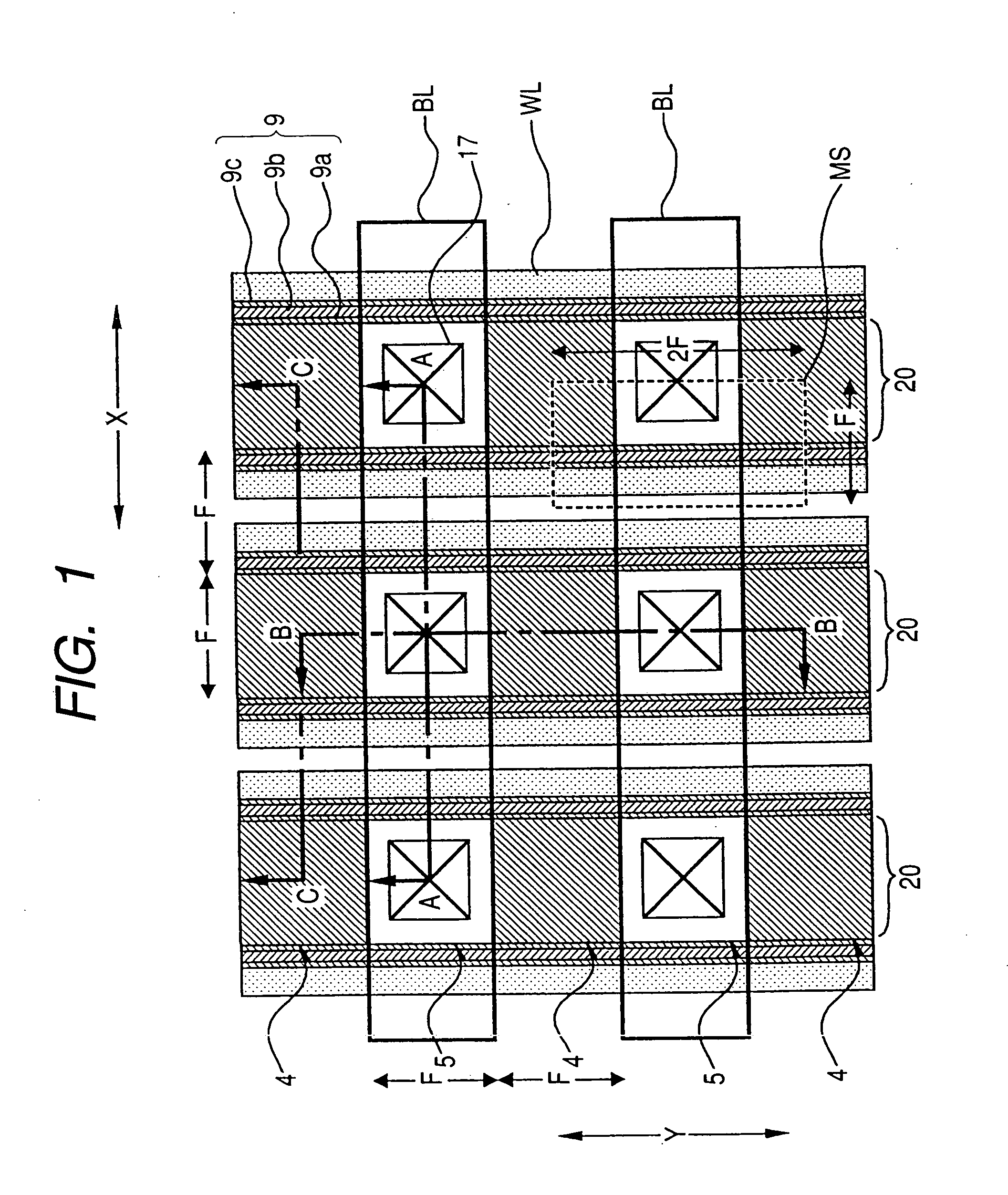
[0083]FIG. 1 is a diagrammatic plan view showing a schematic structure of a memory cell array portion in a flash memory as Embodiment 1 of the present invention.
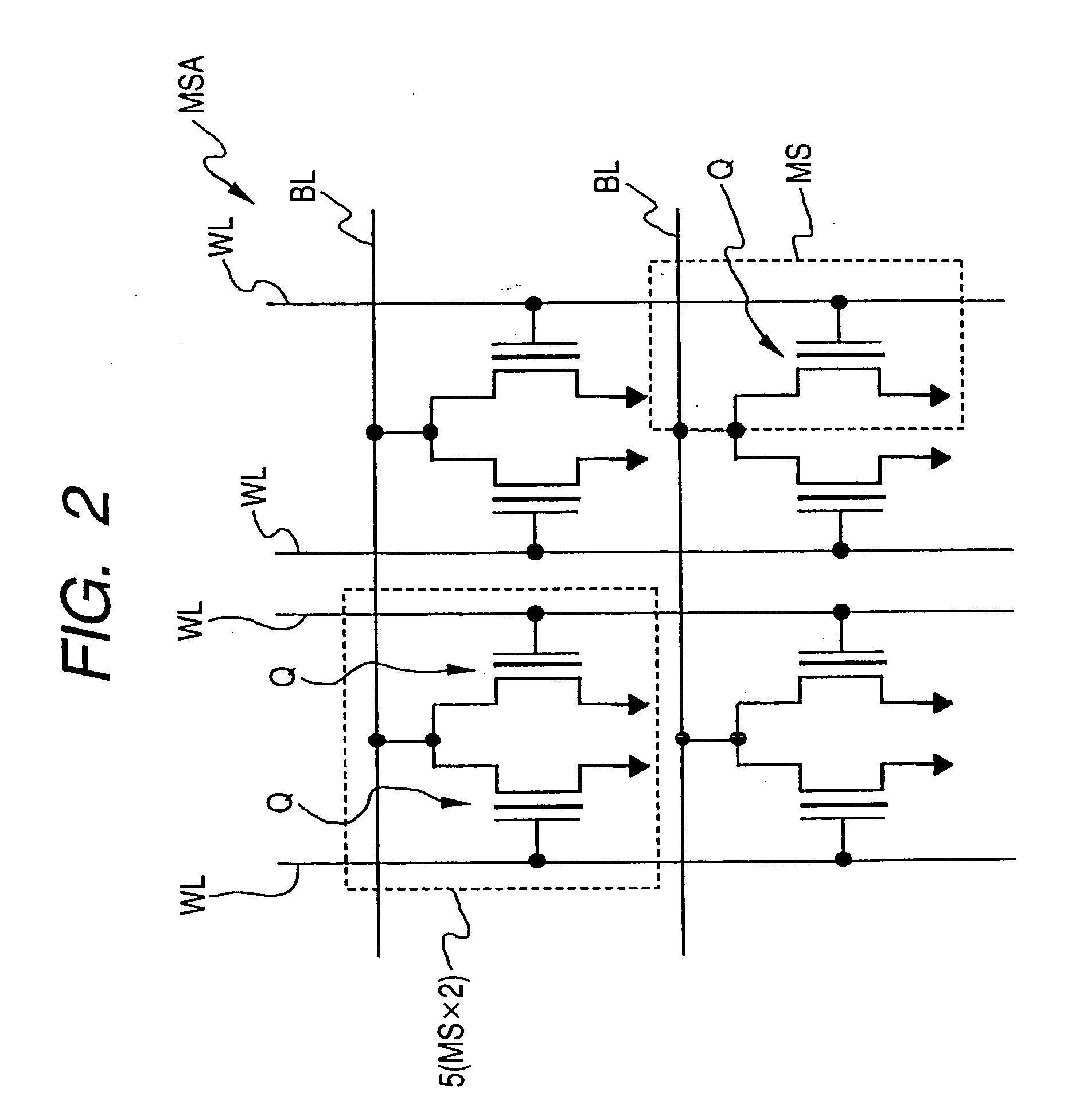
[0084]FIG. 2 is an equivalent circuit diagram of the memory cell array portion of FIG. 1.
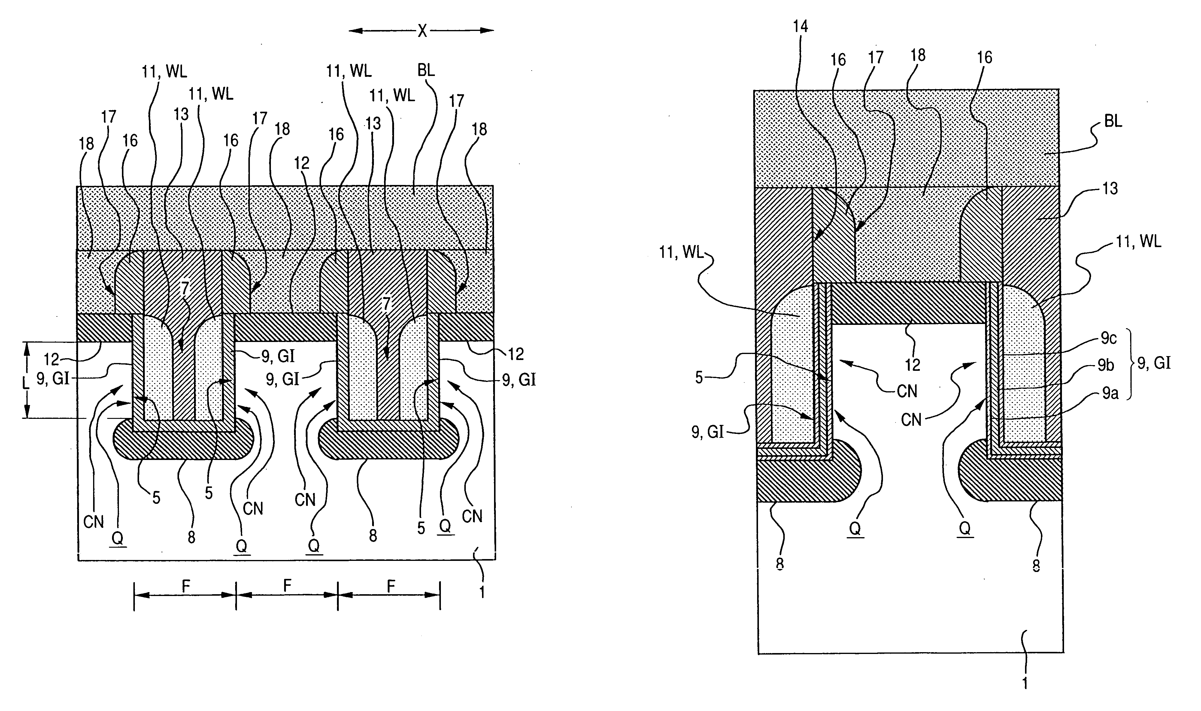
[0085]FIG. 3 is a diagrammatic cross-sectional view along the line A-A of FIG. 1.
[0086]FIG. 4 is a diagrammatic cross-sectional view obtained by enlarging a part of FIG. 1.
[0087]FIG. 5 is a diagrammatic cross-sectional view along the line B-B of FIG. 1.
[0088]FIG. 6 is a diagrammatic cross-sectional view along the line C-C of FIG. 1.
[0089] In the memory cell array portion MSA of the flash memory in the present embodiment, a plurality of word lines WL and a plurality of data lines BL extend, as shown in FIGS. 1 and 2. The plurality of word lines WL extend in the Y-direction and arranged at a given spacing in the X-direction orthogonal to the Y-direction. The plurality of data lines BL extend in the X-direction and arranged at a given...
embodiment 2
[0129] The present embodiment pertains to the connection of electrodes to the control gate electrodes formed as side spacers in the memory cells according to the present application. In FIGS. 23 and 24, plan views of the nonvolatile memory cells according to the present invention are shown schematically. In the drawings, an electrode connecting structure to the control gate electrodes at the edge portions of a memory array is shown, in which rectangular-parallelepiped semiconductor pillars 41 are arranged and trenched isolation regions (insulator pillars) 42 are formed such that every second of them is different in length at the edge portions of the memory array. In the processing of control gate electrodes 45 into side spacers, regions from which the control gate electrodes 45 are extracted are formed by using mask patterns 44 defining the gate electrode of a peripheral circuit and connected to first metal lines 48 via contact holes 47. The placement pitch of the control gate elect...
embodiment 3
[0142] The present embodiment pertains to a method for manufacturing the memory cells according to the present application and the transistor for the peripheral circuit in the same manufacturing process steps, which will be described with reference to the cross-sectional views in the individual manufacturing process steps shown in FIGS. 25 to 33. Each of the cross-sectional views shows a cross section of a peripheral circuit portion and a memory cell portion.
[0143] First, FIG. 25 shows a state in which a trenched isolation region 52 is formed by filling an oxide film in a trench at a depth of 250 nm in a surface region of a p-type semiconductor silicon substrate (hereinafter simply referred to as a silicon substrate) 51 with a resistivity of 10 Ωcm and planarizing it by CMP (Chemical Mechanical Polishing) and then a surface oxide film 53 with a thickness of 10 nm is formed. Through the surface oxide film 53, an n-type well region has been formed by implanting phosphorus ions at an ...
PUM
 Abstract
Description
Claims
Application Information
 - R&D
- Intellectual Property
- Life Sciences
- Materials
- Tech Scout
- Unparalleled Data Quality
- Higher Quality Content
- 60% Fewer Hallucinations
Browse by: Latest US Patents, China's latest patents, Technical Efficacy Thesaurus, Application Domain, Technology Topic, Popular Technical Reports.
© 2025 PatSnap. All rights reserved.Legal|Privacy policy|Modern Slavery Act Transparency Statement|Sitemap|About US| Contact US: help@patsnap.com


