Fluid flow measurement using optical fibres

a technology of optical fibres and fluids, applied in the direction of instruments, survey, borehole/well accessories, etc., to achieve the effect of simple yet straight-forward fabrication, not adversely affecting the flow being measured, and not easy to damag

Inactive Publication Date: 2006-09-28
SCHLUMBERGER TECH CORP
View PDF3 Cites 85 Cited by
  • Summary
  • Abstract
  • Description
  • Claims
  • Application Information

AI Technical Summary

Benefits of technology

[0028] In one embodiment, the heatable coating is provided as a single layer. This is an advantageously simple arrangement, that is straightforward to fabricate. In an alternative arrangement, the heatable coating is provided as two layers, one layer being optically absorptive and one layer being optically dependent on temperature. This is a more complicated configuration, that offers the alternative advantage that the materials of the two layers can be individually selected to provide optimum heating and temperature measuring.
[0029] Advantageously, the optical fibre is disposed within a well bore. Optical fibre sensors are well-suited to the downhole environment of a well bore, particularly oil well bores, and, being compact, do not adversely affect the flow being measured. Also, there are established techniques for deploying fibres into well bores that can be exploited in conjunction with the present invention to provide a simple yet useful oil industry flow monitor.

Problems solved by technology

The resulting device is compact, particularly when compared to known optical fibre-based systems; this is a valuable feature in a flow measuring device because a bulky device tends to disrupt the flow being measured.

Method used


Image

  • Fluid flow measurement using optical fibres
  • Fluid flow measurement using optical fibres
  • Fluid flow measurement using optical fibres

Examples


first embodiment

[0066] A first embodiment of the present invention uses a coated optical fibre as an anemometer to achieve distributed fluid flow monitoring. That is, an indication of flow along the whole length of the fibre can be obtained.

[0067] The invention relies on the cooling effect produced by fluid flowing over a surface that is hotter than the fluid. Heat is transferred from the surface to the fluid at a rate that depends on the flow velocity of the fluid; a faster flow carries more heat away from the surface. Thus, the surface is cooled. A measurement of the resulting surface temperature can therefore provide an indication of the flow velocity, with low temperatures corresponding to high flow velocity.

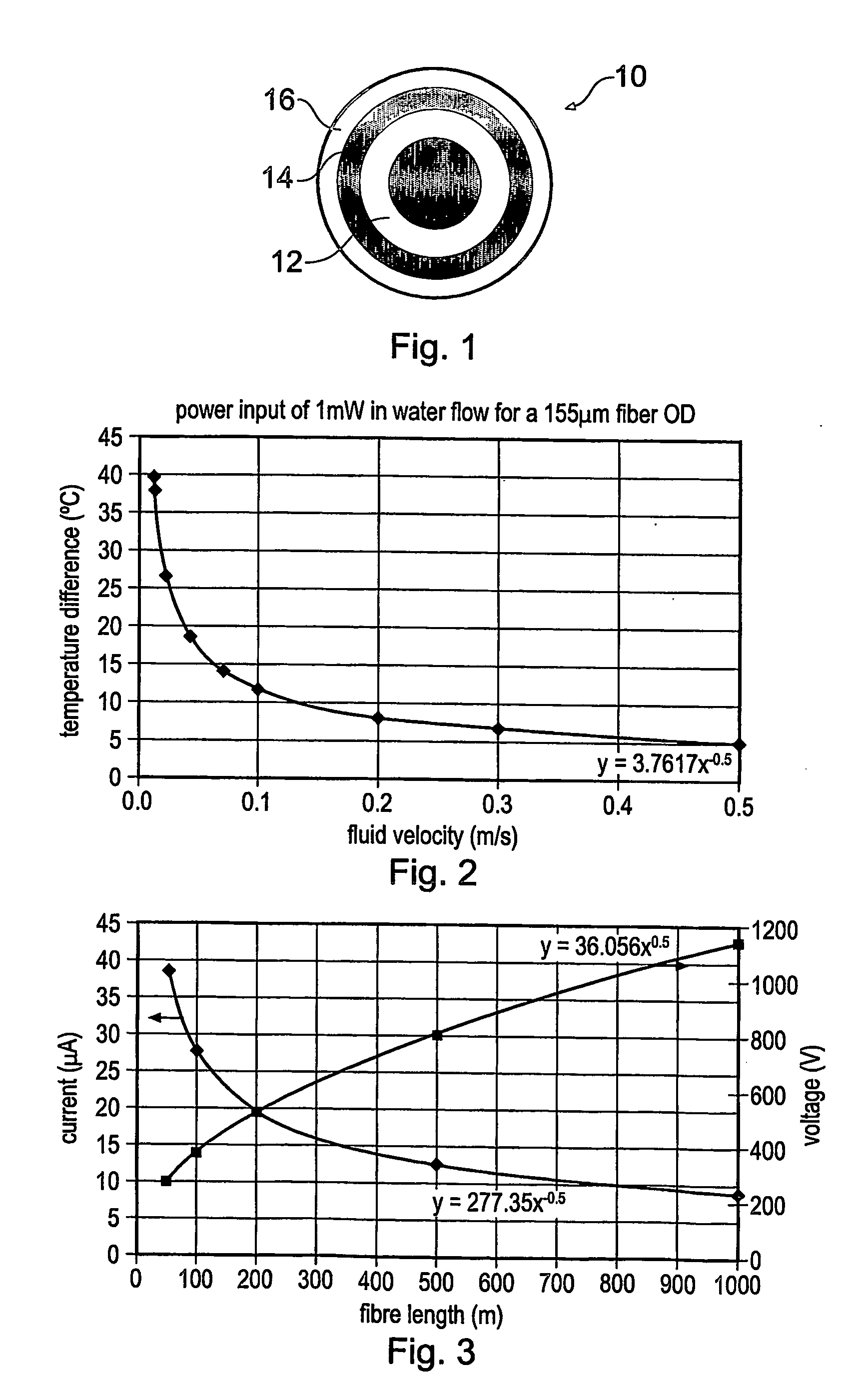
[0068]FIG. 1 shows a transverse cross-section through an optical fibre according to the first embodiment. The optical fibre 10 is a conventional fibre fabricated from silica, with a core surrounded by a cladding region 12 (the details of which are not shown). The fibre 10 has a heatable c...

second embodiment

[0104] A second embodiment of the present invention uses an alternative arrangement of an optical fibre having a heatable coating to monitor or measure fluid flow. In this example, the heatable coating is heated by optical power, and is positioned on an end facet of the fibre. This allows localised, single point measurements to be made. Also, the use of optical power to achieve the heating removes the requirement for electrical power.

[0105]FIG. 11 is a schematic representation of an optical fibre sensor according to the second embodiment. An optical fibre 100 has an end 101 arranged to be placed in a fluid flow. The end 101 is the distal end of the fibre 100 with respect to the user, and has an end facet provided with a thin film coating 102. The coating is of a material that undergoes thermal expansion, so that its optical length (optical thickness of the coating) is a function of temperature. Thus a measurement of its optical length is an indication of its temperature, which give...


PUM

PropertyMeasurementUnit
outer diameteraaaaaaaaaa
absorption coefficientaaaaaaaaaa

Abstract

A method of monitoring fluid flow uses an optical fibre having a heatable coating. The fibre is disposed within flowing fluid, and the heatable coating heated so that heat is transferred from the coating to the fluid. Optical measurements of the temperature of the heatable coating are made, where the temperature of the heatable coating depends on the flow velocity of the flowing fluid, and the temperature measurement is used to derive information about the flow. The coating may be an electrically resistive layer on the outer surface of the fibre, that is heated by passing electric current through it. This allows distributed flow measurements to be made. Alternatively, discrete measurements can be made if the coating is provided as a thin film layer on an end facet of the fibre. The coating is heated by directing light at a wavelength absorbed by the thin film material along the fibre.

Description

BACKGROUND OF THE INVENTION [0001] The present invention relates to the measurement and monitoring of fluid flow, using optical fibres. [0002] The hot wire anemometer has been long known as a device for measuring fluid flow [1]. The device comprises a thin wire typically a few millimetres long which is placed orthogonally to the direction of the flow to be measured. A voltage is applied across the wire, and the resulting current flow through the wire, which is inversely proportional to the resistance according to Ohm's law, heats the wire. This heat is transferred to the fluid at a rate which is dependent on the flow velocity of the fluid, until a final equilibrium temperature of the wire is reached. The wire resistance depends on its temperature, so the current can be related to the flow velocity. Measurement of the current can therefore be used to calculate the flow rate. [0003] The principle of the hot wire anemometer depends on the cooling effect of a fluid flowing past a heated...

Claims


Application Information

Patent Timeline
Patent Type & Authority Applications(United States)
IPC IPC(8): E21B49/08G01F1/68G01V8/16E21B47/09E21B47/10G01F1/688G01K11/32G01P5/10
CPCE21B47/09E21B47/1005G01F1/6884G01K11/32G01P5/10E21B47/103
Inventor RAMOS, ROGERIO
Owner SCHLUMBERGER TECH CORP
Why Eureka
Try Eureka