Positioning system and linear motor

a positioning system and linear motor technology, applied in the direction of instruments, charge manipulation, furnaces, etc., can solve the problems of difficult to achieve prediction, position measurement error, and change in temperature of structural components around the coil, so as to improve response time, reduce temperature distribution on the cooling jacket surface, and improve efficiency. control

Active Publication Date: 2006-10-05
CANON KK
View PDF16 Cites 29 Cited by
  • Summary
  • Abstract
  • Description
  • Claims
  • Application Information

AI Technical Summary

Benefits of technology

[0022] The advantageous effects of the present invention will be more outstanding when the heater is provided on a surface of a cooling jacket which surface is approximately opposed at least to an optical axis (measurement light path) of an interferometric gauge. The heater may preferably comprise a film-like heater, from the standpoint of uniformness of the surface temperature. The heater may be adhered to the cooling jacket through a resin material or a vacuum insulating material, and in that occasion transfer of heat generated by the heater to the cooling medium can be reduced, with a result of more efficient temperature control.
[0023] The temperature of the cooling medium may be set at a level lower than the temperature of airs around the optical axis of the interferometric gauge. In that occasion, even if the amount of heat generation of the coil changes, by controlling the heat generation of the coil the surface temperature of the cooling jacket can be adjusted to the level of the air temperature around the optical axis.
[0024] A plurality of heaters may be provided along the surface of the cooling jacket, and they may be arranged so that the amount of heat generation of each heater can be controlled independently of the others in accordance with the temperature distribution of the cooling jacket. As a result, the temperature distribution on the cooling jacket surface can be reduced effectively.
[0025] A temperature measuring device for measuring the temperature of the surface, or around it, of the cooling medium which surface is approximately opposed at least to the optical axis of an interferometric gauge may be provided to control the amount of heat generation of the heater on the basis of an output of the temperature measuring device. In that occasion, the temperature of the cooling jacket can be adjusted constant with respect to a set temperature.
[0026] In that case, at least a portion of the cooling jacket may be disposed between a stator and a movable element of the linear motor. Particularly, the heater may preferably be provided on the surface of the jacket which surface faces the measurement light path of the interferometric gauge. Alternatively, the heater may be disposed on the surface of the stator or the movable element of the linear motor or, as a further alternative, it may be disposed between a coil and a magnet of the linear motor. As regards the heater, at least the surface of the jacket may be made of an electrically conductive material such that the conductive material may function as the heater when an electric voltage is applied thereto.
[0027] In the present invention, a control system may preferably comprise a drive control system for controlling drive of the linear motor, and a computing system for predicting a temperature change of the temperature adjusting member on the basis of an output of the drive control system, such that the amount of heat generation of the heat generating member can be controlled on the basis of an output of the computing system. With this structure, the heater can be feed-forward controlled and the response time can be improved. Furthermore, without a temperature sensor, the surface temperature of the cooling jacket can be controlled to some extent. Moreover, the present invention can provide larger advantageous effects when the same is applied to a plane motor.

Problems solved by technology

This causes a temperature rise around the coil, which in turn causes a change in temperature of structural components around the coil and, then, deformation of them due to thermal expansion.
Furthermore, where an interferometric gauge such as a laser interferometer is used to measure the position of an article which is going to be positioned, any temperature unevenness around the interferometer optical axis (measurement light path) due to heat generating members such as described above will cause fluctuation of airs around the laser light path, resulting in a position measurement error.
Since, however, the measurement error of laser interferometers attributable to fluctuation of airs is variable quickly as compared with thermal deformation, prediction is very difficult to achieve.
Practical compensation techniques therefor have not been established, for this reason.
Hence, in addition to the air-conditioning design, reducing temperature unevenness due to heat generating members is a very critical issue.
However, generation of uneven temperature between the upstream side and downstream side of the jacket is inevitable in principle, and there is a limit to suppress fluctuation of airs.
This means that the magnetic gap becomes very large, and thus the efficiency of the linear motor becomes slow.
Namely, to obtain the same thrust, a larger structure is required as compared with the structure of FIG. 7, and larger heat generation results therefrom.
In that occasion, however, the interspace between the magnet (not shown) and the coil becomes large, and the linear motor efficiency becomes quite slow.
Although conventional structures for reducing temperature unevenness on the linear motor jacket surface as disclosed in some patent documents have been described hereinbefore, all of these structures involve inconveniences such as limitation in regard to temperature precision, need of a very complicated structure, or sacrificing the linear motor efficiency.
Hence, these are not impracticable.

Method used


Image

  • Positioning system and linear motor
  • Positioning system and linear motor
  • Positioning system and linear motor

Examples


embodiment 1

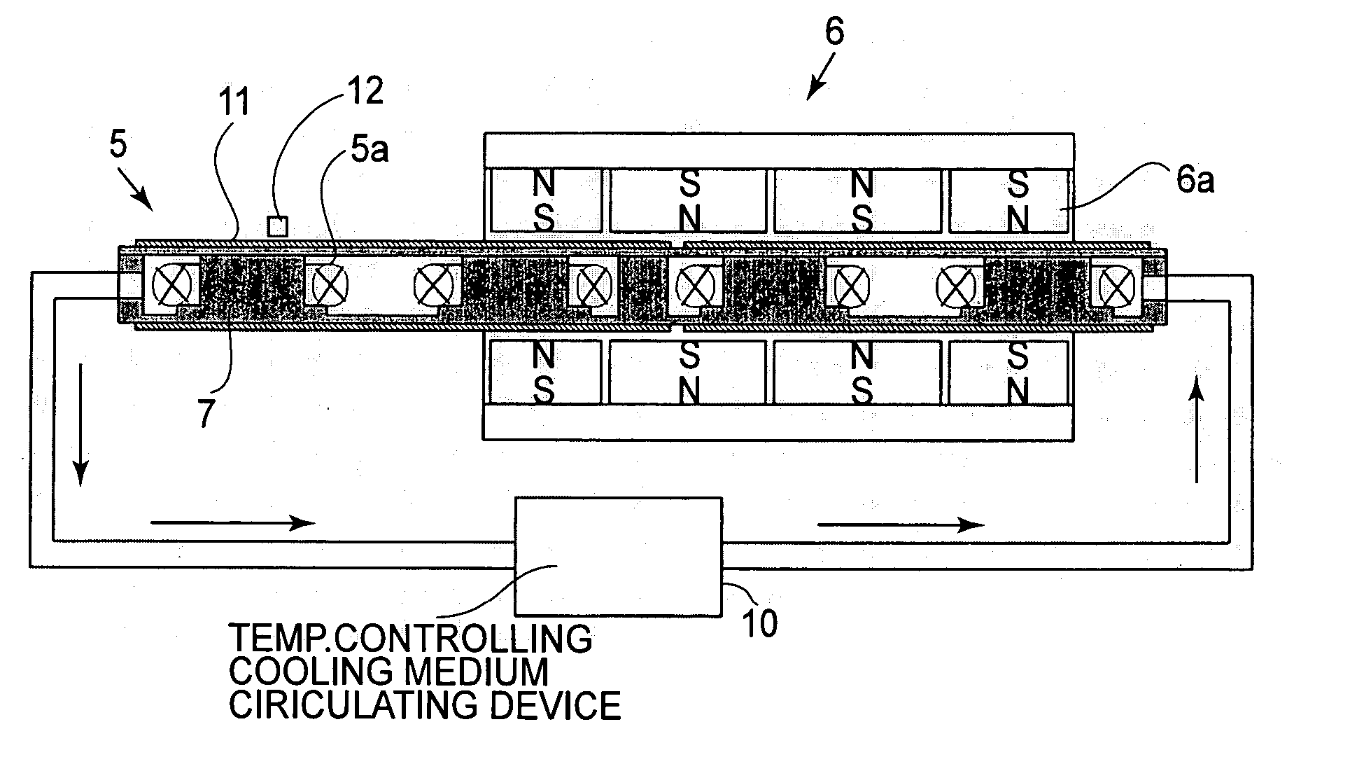
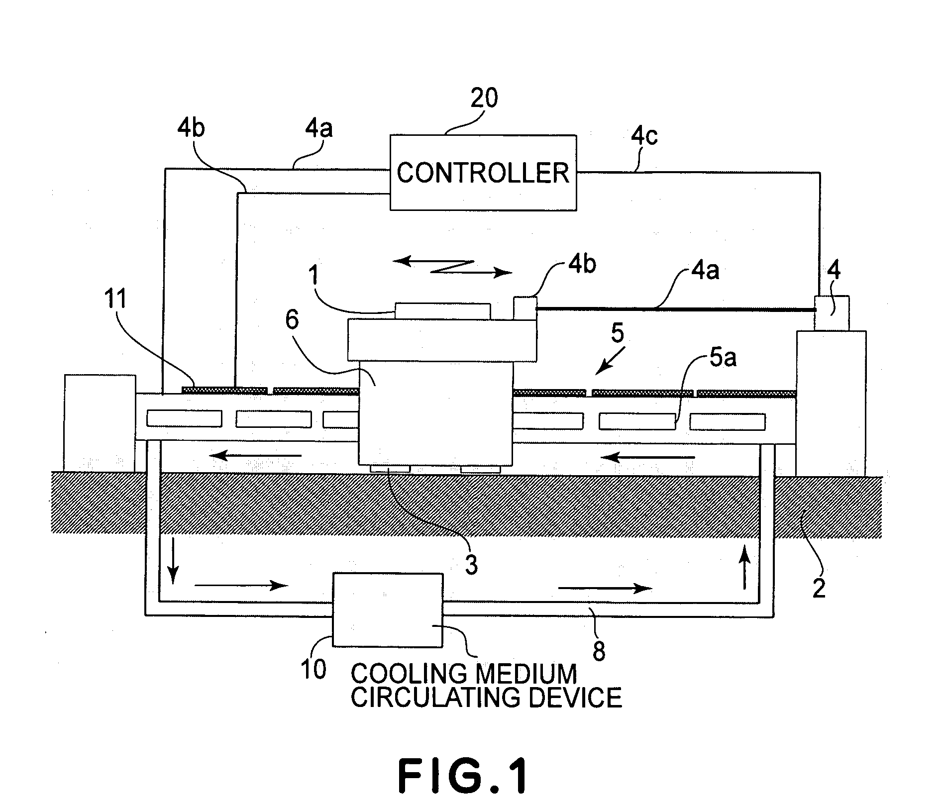
[0042] A first embodiment of the present invention will be explained with reference to FIG. 1. FIG. 1 shows a linear motor and a positioning system having an interferometric gauge for position measurement. In this embodiment, the invention is applied to a positioning system in which the position of an object to be positioned is measured by use of a laser interferometer, wherein the positioning system includes a heat generating portion and a temperature adjusting member having a cooling system for collecting heat generated from the heat generating portion by use of a cooling medium. The temperature adjusting member is disposed adjacent the optical axis of the laser interferometer, and the heat generating portion is provided to the surface of the temperature adjusting member.

[0043] In FIG. 1, the object 1 which is going to be positioned is floated with respect to a base table 2 by means of a static bearing 3 on one hand, and it is guided by the base table 2 on the other hand, such th...

embodiment 2

[0057] A second embodiment of the present invention will be described with reference to FIG. 3. FIG. 3 shows a wafer positioning system having a dual-axis drive rough-motion stage and a six-axis drive fine-motion stage mounted on the rough-motion stage. The dual-axis rough-motion stage denoted at 31 is driven in X and Y directions by means of four linear motors 32, two for the X axis and two for the Y axis. As a notable feature of this structure, the object to be positioned is surrounded by the four linear motors, as shown in the drawing.

[0058] Generally, a rough-motion linear motor is the largest heat generating source in the positioning system and, in the case of FIG. 3, it is the four linear motors surrounding the object to be positioned. In the structure of this example, the heat source is preferably disposed far from a wafer 33 which is the object to be positioned and which should be kept away from the influence of heat. However, in relation to the position measurement using a...

embodiment 3

[0061] Next, a third embodiment of the present invention will be described with reference to FIG. 4. FIG. 4 shows an example wherein the present invention is applied to a plane motor, that is, a linear motor structure having simultaneous drivability with respect to two or more axial directions. Here, a plan motor disclosed in Japanese Laid-Open Patent Application, Publication No. 2004-254489 is taken as an example.

[0062]FIG. 4 illustrates a sectional view of a plan motor, with a portion being omitted. A wafer 42 which is the object to be positioned is supported on a movable element 42 that comprises two-dimensionally arrayed magnet groups 42a, a top plate 42b above the magnet groups, and a chuck 42c. A stator 43 is disposed opposed to the movable member 42 and it comprises a plurality of elongated coils 43a corresponding to the magnet groups 42a. Each coil 43a has a dual-layer structure, for example, comprising a first coil layer extending in the X direction and a second coil layer...


PUM


Abstract

Disclosed is a positioning system and an exposure apparatus having the same, wherein in accordance with an aspect of the present invention the positioning system includes a stage being movable and being configured to carry an object thereon, an interferometer configured to measure a position of the stage, a driving system configured to drive the stage, and a heater provided between a light path of the interferometer and a coil which is a component element of the driving system. In one preferred form of the present invention, the heater has a film-like shape or it is formed as a portion of a cooling jacket that is configured to cover the coil.

Description

FIELD OF THE INVENTION AND RELATED ART [0001] This invention relates to a precision positioning system such as an X-Y table to be used in a semiconductor exposure apparatus, a surface shape measuring apparatus or a high-precision machining apparatus, for example, or to a linear motor suitably usable in such positioning system. More specifically, in an aspect, the invention concerns a temperature controlling structure in such positioning system, for avoiding or reducing adverse influence of heat generated from a driving system for moving an article to be positioned, upon an interferometric gauge. [0002] Recent exposure apparatuses use a linear motor as a driving source for a reticle stage, a wafer stage and so on. From the standpoint of the principle employed, these linear motors may be categorized into Lawrence type, pulse motor type, induction type and so on. Anyway, the term “linear motor” generally refers to a driving source configured to directly apply straight motion (reciproca...

Claims


Application Information

Patent Timeline
Patent Type & Authority Applications(United States)
IPC IPC(8): H02K9/00H02K41/00B23Q5/28B65G49/07H01L21/68H02K9/19H02K41/03H02P25/06
CPCG03F7/70758G03F7/70775H02K41/03H02K9/005H02K15/125G03F7/70858H02K9/00
Inventor EMOTO, KEIJI
Owner CANON KK
Why Eureka
Try Eureka