Production of nickel nanoparticles from a nickel precursor via laser pyrolysis

a technology of laser pyrolysis and nickel nanoparticles, which is applied in the field of production of nickel nanoparticles, can solve problems such as detriment to magnetic properties, and achieve the effects of increasing co flow rate, increasing production rate first, and increasing flow ra

Inactive Publication Date: 2006-10-12
THE RES FOUND OF STATE UNIV OF NEW YORK
View PDF40 Cites 46 Cited by
  • Summary
  • Abstract
  • Description
  • Claims
  • Application Information

AI Technical Summary

Benefits of technology

[0047] After regenerating the nickel powder in the nickel carbonyl generator with flowing H2 at about 300° C., carbon monoxide (CO) can react with the active nickel surface to form nickel carbonyl at room temperature. The concentration and flow rate of Ni(CO)4 into the laser-driven reactor can be changed by varying the CO flow rate, and this, in turn, affects the production rate and the average size of the nickel nanoparticles. FIG. 3 shows the results that were obtained by fixing all other operating parameters and changing only the CO flow rate. The operating conditions are listed in Table 1. The average size obtained from XRD and BET experiments shown in FIG. 3 are different, since XRD estimates the average crystalline domain size, but nitrogen physisorption (the BET method) measures the specific surface area of the sample. From the surface area, the average particle size was calculated assuming that the particles are spheres with the density of bulk nickel. Both of these methods of estimating average particle size show the same trend in particle size with respect to changes in the CO flow rate. TABLE 1Typical Reaction ParametersOperatingSF6 (inlet)SF6 (sheath)He (sheath)Purge He FlowPressureflow rateflow rateflow rateRate12.0˜12.1 psia11.9 sccm2.6 sccm145 sccm1300 sccm
[0048] With increasing CO flow rate (from 30, 60, 100, 150, 250, 350 to 450 sccm), the production rate first increased and then decreased. This can be rationalized as follows. The main factor determining the production rate at low CO flow rates is the supply of Ni(CO)4 to the reactor. When the CO flow rate was lower than 150 sccm, the total supply of Ni(CO)4 to the reactor increased with increasing flow rate. However, when the CO flow rate increased more, even though the absolute Ni(CO)4 flow rate may have continued to increase, the concentration of Ni(CO)4 in the precursor stream decreased, if the kinetics of Ni(CO)4 generation from Ni and CO in the generator limited the production rate of Ni(CO)4. With higher flow rates, the residence time in the laser beam was shorter, and a smaller fraction of the Ni(CO)4 entering the reactor was converted to particles. Therefore, the production rate decreased with further increase in CO flow. For the average particle size, the residence time and Ni(CO)4 concentration are more important than the total supply of Ni(CO)4 to the reactor. With increasing CO flow rate, the residence time and Ni(CO)4 concentration decreased and, as a result, the average particle size decreased. When the CO flow rate was higher than 250 sccm, the average particle size increased slightly with increasing CO flow rate.
[0049] Particles were increasingly prone to deposit on the inlet nozzle at higher CO flow rates. Deposition of particles on the nozzle and reactor walls also contributed to the apparent decrease in production rate, since these particles were not collected. TEM was used to characterize the size and morphology of these nickel particles. FIG. 4 and FIG. 5 show TEM images and selected area electron diffraction patterns (inset) from two samples produced with 100 and 250 sccm CO flow rates, respectively. The SAED pattern in FIG. 5 was taken from the larger particles in the TEM image. From the TEM images, it is clear that for the larger CO flow rate, some large, agglomerated, and (partially) fused particles are present. On the basis of these results, the increase in average particle size and the increasing tendency for particles to deposit on the inlet nozzle at high flow rates can be attributed to recirculation of gases in the top of the reactor. As shown schematically in FIG. 2, there is potential for recirculation of gases in the region above the laser beam. Presumably, with increasing CO flow rate, the recirculation of mixed gases already containing nickel nanoparticles was stronger. Reheating of these recirculated particles then led to their growth and (partial) sintering to form larger particles with nonspherical shape. At the same time, some recirculated particles were deposited on the nozzle and reactor walls. The average particle size increased as a result, even as the particle size for non-recirculated particles continued to decrease slightly.
[0050] In FIGS. 4 and 5, as well as other TEM images shown herein, the nickel nanoparticles were substantially agglomerated. Because the particles were produced at high number concentrations, estimated to be about 1011 particles per cm3 for typical conditions within the reactor, some coagulation prior to collection downstream is inevitable. Because the TEM grids were prepared from particle dispersions, it was not clear how much coagulation occured in the reactor system and how much occured during solvent evaporation when the TEM grids were prepared. Direct thermophoretic sampling onto TEM grids within or just after the reactor would allow this question to be addressed.
[0051] Wide-angle powder X-ray diffraction (XRD) was also used to characterize all of these samples. The results were identical except for the slight changes in peak width reflected in the size estimates shown in FIG. 3. FIG. 6 shows the X-ray diffraction pattern from the sample that was prepared at a CO flow rate of 100 sccm. All of these samples showed the major characteristic peaks for pure crystalline metallic nickel at 2θ values of 44.5 [Ni-111] and 51.8 [Ni-200] degrees. This indicates that there was no significant amount of crystalline NiO or other crystalline material formed, and that there was not a large amount of amorphous material present, since no broad peaks indicative of an amorphous phase were observed.
[0052] An inert gas was used both as the sheath gas (entering the reactor in the concentric inlet surrounding the precursor inlet) and as the purge gas (entering the reactor at the ends of the four horizontal arms of the six-way cross) during particle synthesis. Experiments to compare helium (He) with argon (Ar) as sheath gas and purge gas in the system are described herein. Table 2 lists the operating parameters used in the experiments and the resulting production rate and mean particle size. The average size is based on XRD peak broadening. TABLE 2Effect of Sheath and Purge Gas PropertiesOperatingSF6 (inlet) flowCO flowSheath flowPurge flowPressureraterateraterate12.0˜12.1 psia4.0 sccm100 sccm580 sccm1300 sccmExperiment (1): Using HeliumExperiment (2): Using ArgonProduction360mg / hr140mg / hrRateAverage17.4nm19.8nmSize

Problems solved by technology

Thus, the particles are devoid of any magnetic dead layers, which may be detrimental to the magnetic properties.

Method used


Image

  • Production of nickel nanoparticles from a nickel precursor via laser pyrolysis
  • Production of nickel nanoparticles from a nickel precursor via laser pyrolysis
  • Production of nickel nanoparticles from a nickel precursor via laser pyrolysis

Examples


example 1

Experimental Methods

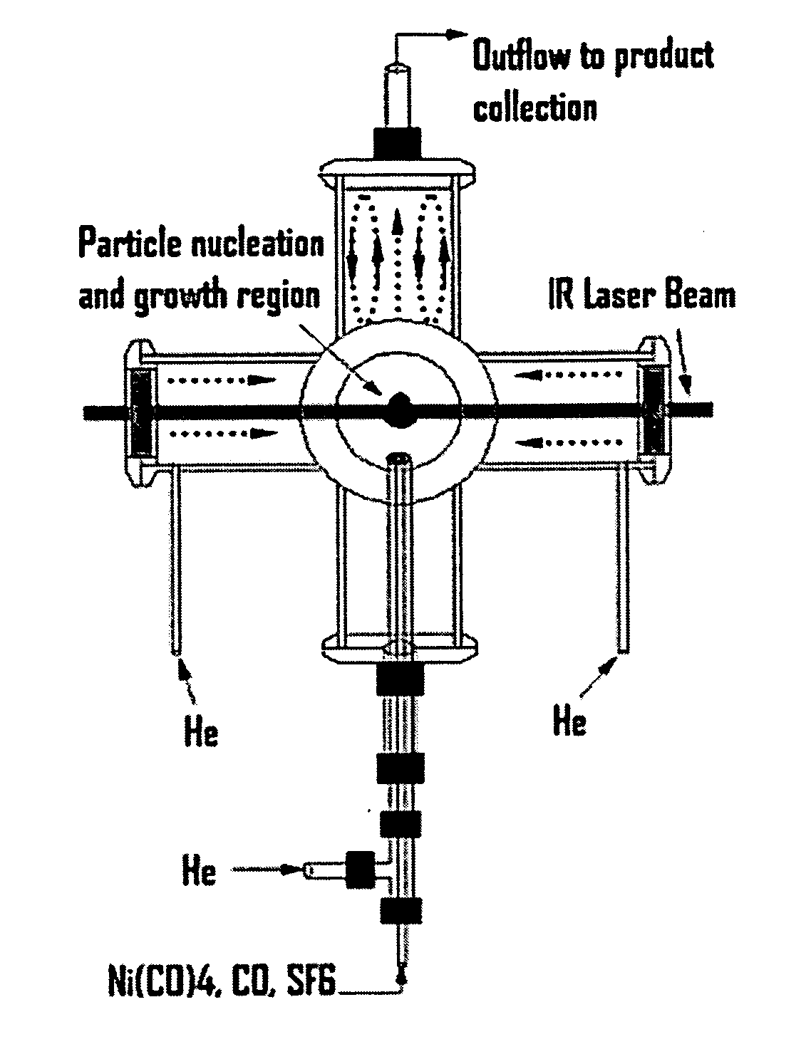
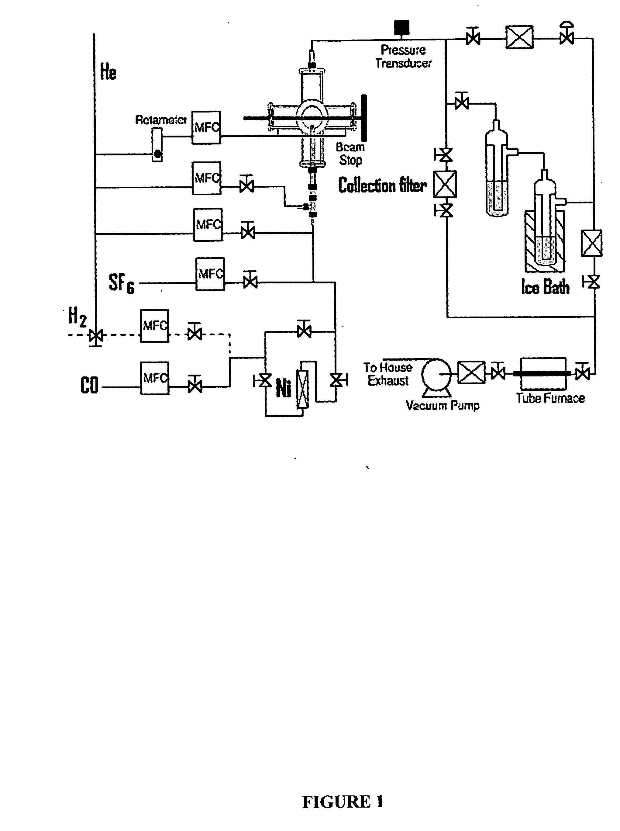
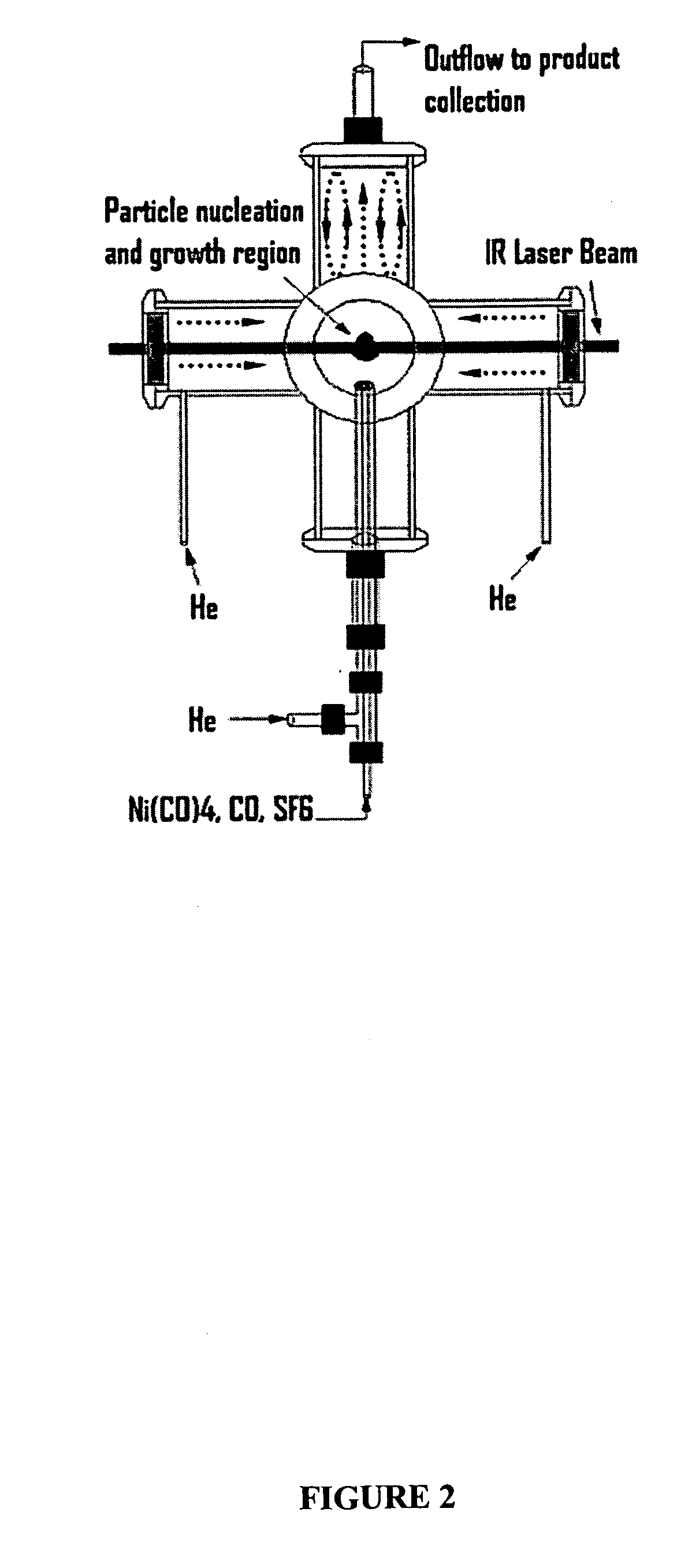
[0043] The reactor configuration shown in FIGS. 1 and 2 was used to prepare nickel nanoparticles in the experiments described herein. Because nickel carbonyl is highly toxic, it was generated in situ by flowing CO through a tube packed with nickel powder, which was placed inside of a tube furnace. This safe and convenient method was applied to generate a small flow of nickel carbonyl to the reactor without maintaining any inventory of nickel carbonyl. Details of this nickel carbonyl generator were as follows. About 605 g of nickel powder (laboratory grade, reduced powder, Fisher Chemicals, Fairlawn, N.J.) was packed into a 1-inch o.d. stainless steel tube with a packed length of about 14 inches. Glass wool and a porous frit were packed at both ends to prevent the nickel powder from leaving the tube. This nickel powder was heated to 300-350° C. in a stream of flowing H2 (250 sccm) for at least 60 minutes to remove any oxide on the nickel surface. The tube was the...

example 2

Collection of Nickel Particles

[0046] The nickel particles collected on filters were loosely agglomerated and black in color. They were attracted to a permanent magnet, both as a powder and when dispersed in a solvent. They were readily dispersed in nonpolar solvents, such as toluene or hexane, and their dispersion was improved by the addition of oleic acid or oleyl amine. However, they did not form colloidal dispersions with long-term stability. Over a period of hours to days, depending on particle size, presence of surfactant, and particle preparation conditions, particles agglomerated and sedimented out of solution. This process was accelerated in the presence of a magnetic field. Many parameters, such as gas flow rates, the carbonyl generator temperature, and the gases used as the photosensitizer and sheath gas, can affect the nanoparticle production rate, size, and morphology.

example 3

Effect of Carbon Monoxide (CO) Flow Rate

[0047] After regenerating the nickel powder in the nickel carbonyl generator with flowing H2 at about 300° C., carbon monoxide (CO) can react with the active nickel surface to form nickel carbonyl at room temperature. The concentration and flow rate of Ni(CO)4 into the laser-driven reactor can be changed by varying the CO flow rate, and this, in turn, affects the production rate and the average size of the nickel nanoparticles. FIG. 3 shows the results that were obtained by fixing all other operating parameters and changing only the CO flow rate. The operating conditions are listed in Table 1. The average size obtained from XRD and BET experiments shown in FIG. 3 are different, since XRD estimates the average crystalline domain size, but nitrogen physisorption (the BET method) measures the specific surface area of the sample. From the surface area, the average particle size was calculated assuming that the particles are spheres with the densi...


PUM

PropertyMeasurementUnit
diameteraaaaaaaaaa
diameteraaaaaaaaaa
diameteraaaaaaaaaa

Abstract

The present invention discloses a process for producing nickel nanoparticles. The process involves heating a nickel precursor generated in situ in the presence of a carrier gas under conditions effective to decompose the nickel precursor and produce nickel nanoparticles.

Description

[0001] This application claims the benefit of U.S. Provisional Patent Application Ser. No. 60 / 618,288, filed Oct. 13, 2004, which is hereby incorporated by reference in its entirety.FIELD OF THE INVENTION [0002] The present invention relates to a process for producing nickel nanoparticles. BACKGROUND OF THE INVENTION [0003] There is an intense and growing interest in the development of nanostructured magnetic materials, motivated primarily by the immense potential of these materials in a broad range of applications including data storage, spintronics, biomedicine, and telecommunications (Pileni, Advanced Functional Materials 11:323 (2001); Leslie-Pelecky and Rieke, Chem. Mater. 8:1770 (1996); Skomski, J. Phys. Condens. Matter. 15:R841-R896 (2003); Prasad, Nanophotonics John Wiley & Sons, New York (2004)). The synthesis and characterization of such materials are also important for basic science in that they can provide insight into the fundamentals of surface chemistry and magnetic i...

Claims


Application Information

Patent Timeline
Patent Type & Authority Applications(United States)
IPC IPC(8): B22F9/00
CPCB22F9/305B22F2999/00B22F2202/11B22F2201/013B22F2201/02B22F2201/04B22F2201/11B22F2201/12
Inventor SWIHART, MARK T.HE, YUANQINGLI, XUEGENG
Owner THE RES FOUND OF STATE UNIV OF NEW YORK
Why Eureka
Try Eureka