

Fuel cell and membrane electrode assembly
- Summary
- Abstract
- Description
- Claims
- Application Information
AI Technical Summary
Benefits of technology
Problems solved by technology
Method used
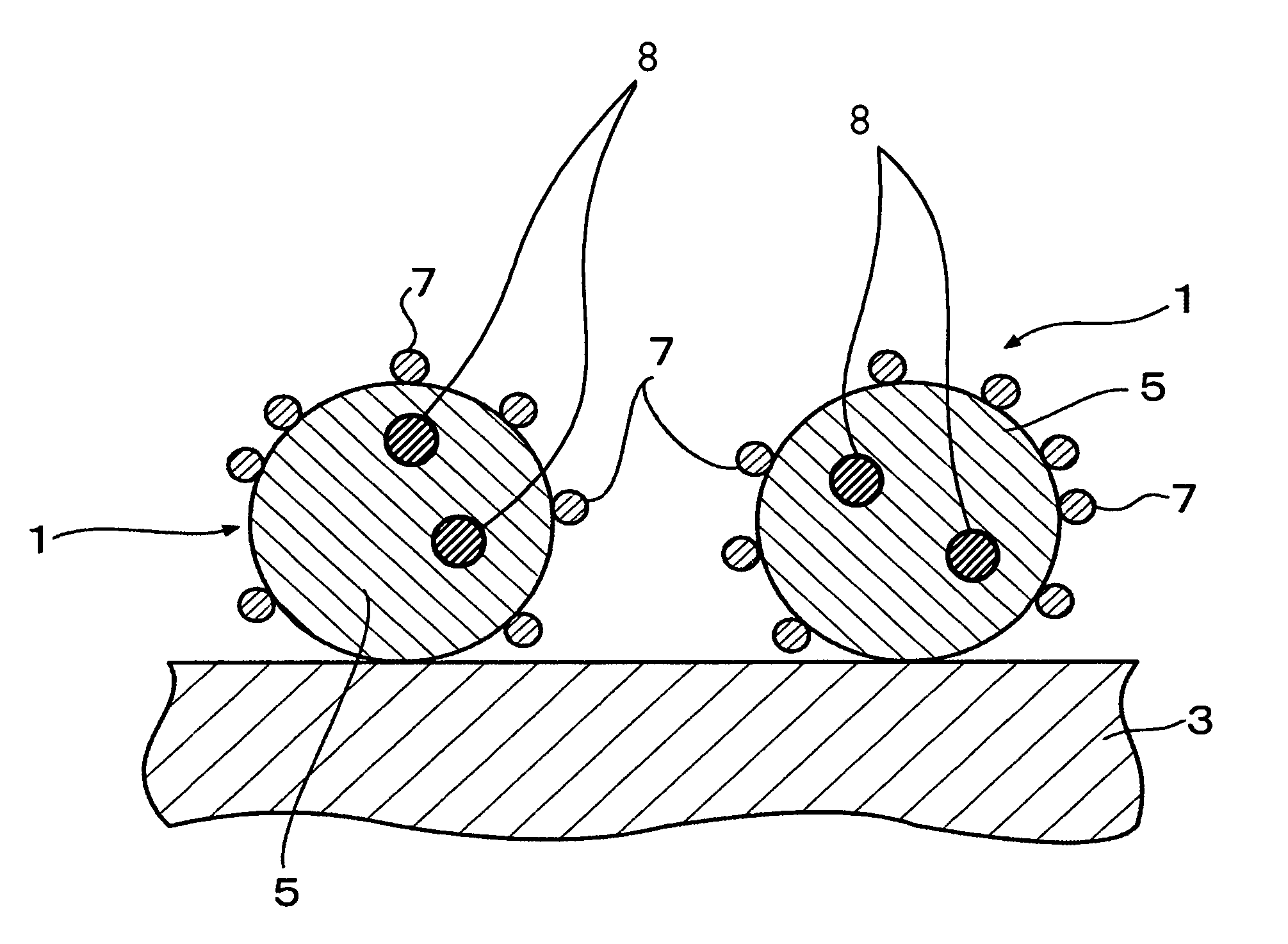
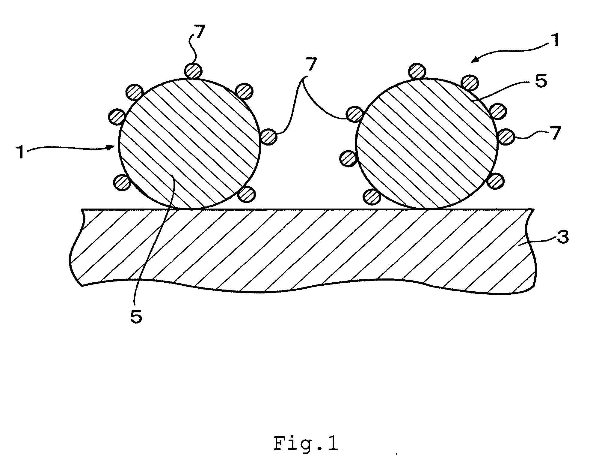
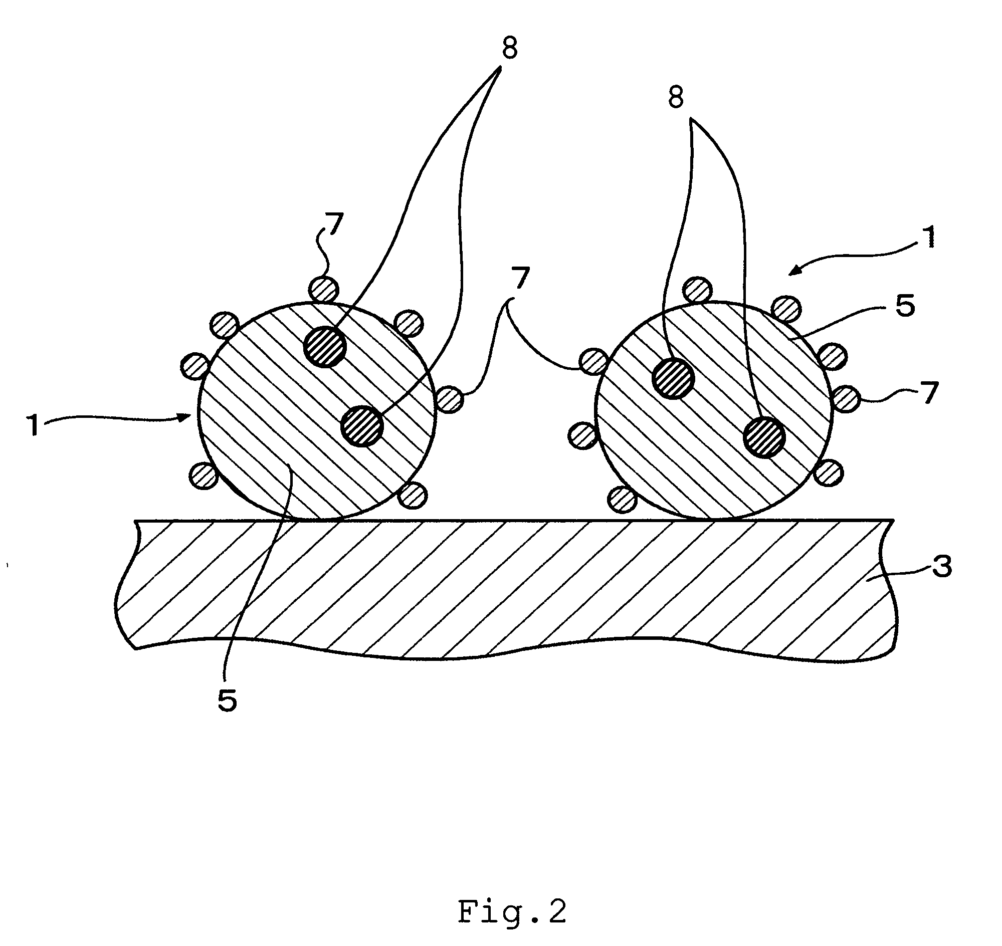
Image

Examples
example 1
[0070] Bis(acetylacetonato)platinum(II) of 1.69 mmol, tris(acetylacetonato)ruthenium(III) of 1.69 mmol, and sodium phosphinate of 0.338 mmol were dissolved into ethylene glycol of 300 ml. An ethylene glycol solution of 100 ml into which a carbon support of 0.5 g (Vulcan XC-72R available from E-TEK Inc., Somerset, N.J., with the specific surface area of 254 m2 / g) was dispersed was added thereto. A sulfuric acid solution was added, and the pH value of the solution was adjusted to 3 using a pH litmus paper. In a nitrogen gas atmosphere, the solution was stirred and refluxed for 4 hours at 200° C., thereby depositing Pt—Ru—P catalyst particulates on the carbon support. Subsequent filtration, washing, and drying gave a catalyst.
example 2
[0071] Bis(acetylacetonato)platinum(II) of 1.69 mmol, tris(acetylacetonato)ruthenium(III) of 1.69 mmol, and sodium dihydrogenphosphite of 0.338 mmol were dissolved into ethylene glycol of 300 ml. An ethylene glycol solution of 100 ml into which a carbon support of 0.5 g (Vulcan XC-72R with the specific surface area of 254 m2 / g) was dispersed was added thereto. A sulfuric acid solution was added, and the pH value of the solution was adjusted to 3 using a pH litmus paper. In a nitrogen gas atmosphere, the solution was stirred and refluxed for 4 hours at 200° C., thereby depositing Pt—Ru—P catalyst particulates on the carbon support. Subsequent filtration, washing, and drying gave a catalyst.
example 3
[0081] An alcohol solution of pure water and NAFION® dispersion solution, available from E.I. DuPont de Nemours and Company, Wilmington, Del., was added to the Pt—Ru—P catalyst deposited on the Vulcan XC-72R obtained in inventive example 1 and stirred, and then its viscosity was adjusted to create a catalyst ink. The catalyst ink was then applied onto TEFLON® sheet, available also from Dupont, in such a way that the amount of the Pt—Ru—P catalyst is 5 mg / cm2. After being dried, the TEFLON® sheet was peeled off, thereby creating a methanol electrode catalyst. Further, an alcohol solution of pure water and NAFION® dispersion solution was added to the Pt catalyst deposited on Ketjen EC, available from Ketjen Black International. Co., Tokyo, Japan, and stirred, and then its viscosity was adjusted to create a catalyst ink. The catalyst ink was then applied onto TEFLON® sheet in such a way that the amount of the Pt catalyst is 5 mg / cm2. After being dried, the TEFLON® sheet was peeled off,...
PUM
| Property | Measurement | Unit |
|---|---|---|
| Diameter | aaaaa | aaaaa |
| Specific surface area | aaaaa | aaaaa |
| Volume | aaaaa | aaaaa |
Abstract
Description
Claims
Application Information