Microchannel heat exchanger with micro-encapsulated phase change material for high flux cooling

Active Publication Date: 2006-10-19
FARID MOHAMMED MEHDI +1
View PDF37 Cites 69 Cited by
  • Summary
  • Abstract
  • Description
  • Claims
  • Application Information

AI Technical Summary

Benefits of technology

[0007] In one embodiment, the present invention provides a practical system for greatly enhancing the cooling efficiency of a microchannel heat exchanger by utilizing MEPCM suspended in the heat transfer liquid passing through the microchannels. The thermal storage advantage of solid PCM is coupled with the high heat flux capabilities of microchannels to achieve high heat flux with little temperature variation in the coolant medium. Advantages of the present invention include the capabilities for a low slurry flow rate and a low pressure drop across the microchannel heat exchanger leading to low pumping or compression power requirements for the thermal transfer apparatus.
[0010] Accordingly, the present invention may provide a heat generating component, e.g., an IC, joined in heat transferring proximity to a microchannel heat exchanger comprising a series of microchannels passing a slurry having a two component fluid of liquid and suspended solids, and desirably containing a liquid / solid phase change material operable to melt in the heat range required for cooling the heat generating component. Desirably, the operating temperature of the coolant fluid will be centered on the melting point of the MEPCM. A pump for moving the liquid slurry through the heat exchanger can then be run with less power due to a lower flow rate required of the coolant than was heretofore available.
[0011] In some embodiments the present invention may provide the heat exchanger with an inlet and an outlet, and operate the heat exchanger to produce a small temperature difference of the slurry between the inlet and the outlet, such as about 5° C. or less to about 20° C. Accordingly, the pressure drop over the heat exchanger will be small and a substantially constant flow rate can be maintained whereby the pumping power requirements will be smaller than for a typical water or ethylene glycol / water mixture alone to achieve an equal or better cooling.
[0014] Accordingly, the present invention can overcome the disadvantages of an evaporative (liquid / vapor) microchannel system by removing the possibility of break down of fluid cooling at high temperatures such as might occur in an liquid-to-vapor phase change system due to a loss of capillary pumping or lack of wetting of the microchannels. Also, unlike the previously used liquid / boiling phase change, the solid / liquid phase change does not create low thermal conductivity vapor near the surface to be cooled.

Problems solved by technology

To Applicants' knowledge, no teaching exists within the art to use MEPCM in a microchannel heat exchanger because physical constraints such as flow conditions, including but not limited to laminar flow versus turbulent flow, viscosity problems, particle clogging, and the like; in a micro-channel environment have not suggested a practical use for a MEPCM slurry to achieve a balancing of the related and interdependent factors of PCM particle size and heat capacity with that of channel size and flow conditions necessary to achieve a small volume, low power microchannel heat transfer apparatus to obtain suitable heat transfer.

Method used


Image

  • Microchannel heat exchanger with micro-encapsulated phase change material for high flux cooling
  • Microchannel heat exchanger with micro-encapsulated phase change material for high flux cooling
  • Microchannel heat exchanger with micro-encapsulated phase change material for high flux cooling

Examples


example 2

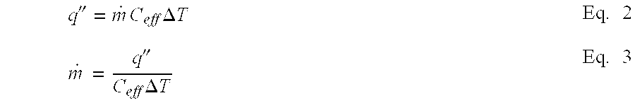
[0046] Suspension: water and microencapsulated Heptadecane [0047] Mass fraction of PCM: 30wt % [0048] Latent heat of PCM: 237 kJ / kg [0049] Microchannel heat exchanger dimensions: [0050] Length: 2 cm [0051] Width: 1 cm [0052] Channel height: 1 cm [0053] Channel width: 400 micron [0054] Channel wall thickness: 200 micron [0055] Number of channels: 16 [0056] Allowable temperature increase of the suspension: 10° C. [0057] Achievable heat flux: 200 W / cm2 [0058] Effective specific heat capacity of the slurry based on 10° C. temperature rise: 10.7 kJ / kg° C.

[0059] Ratio of the effective specific heat capacity of slurry to that of pure water: 2.6

Water coolingwater / PCMParameterin microchannelslurry coolingFluid velocity1.5m / s0.64m / sReynolds number717281Pressure drop3.5kPa1.5kPaPumping power33.6mW6.1mW

[0060] The above comparison shows that by replacing the water with PCM slurry, the pressure drop was reduced to more than half, reducing the pumping power requirement by about five times while...


PUM

PropertyMeasurementUnit
melting pointaaaaaaaaaa
temperatureaaaaaaaaaa
heightaaaaaaaaaa

Abstract

A microchannel cooler containing a slurry having a particulate liquid / solid phase change material is provided balancing the interdependent factors of microencapsulated particle size with microchannel size and shape and flow conditions for the removal of high heat flux with low space and low power requirements.

Description

FIELD OF THE INVENTION [0001] This invention relates generally to the removal of heat from volume or power constrained environments and, more particularly, to microchannel coolers suitable for the removal of high heat flux with low space and low power requirements. BACKGROUND OF THE INVENTION [0002] Technology advances in microchips, batteries, and various other small scale and high power applications are increasingly constrained by the need for effective thermal management. For example, increasing the speed of microprocessors may depend on effective new thermal management techniques to dissipate high heat fluxes. Similarly, electronic actuators that may take the place of hydraulics and mechanical actuators in aircraft may require similarly effective thermal management schemes. It is desirable that these thermal management, i.e., thermal transfer, schemes meet the criteria of low power consumption, low physical volume, and low weight owing to the small scale of many intended applica...

Claims


Application Information

Patent Timeline
Patent Type & Authority Applications(United States)
IPC IPC(8): F28D19/00
CPCF28D15/0266F28D20/023F28F2260/02H01L23/427H01L23/473H01L2924/0002Y02E60/145H01L2924/00Y02E60/14
Inventor FARID, MOHAMMED MEHDIAL-HALLAJ, SAID
Owner FARID MOHAMMED MEHDI
Why Eureka
Try Eureka