Liquid crystal display device
a liquid crystal display and display device technology, applied in static indicating devices, non-linear optics, instruments, etc., can solve the problems of poor moving image performance of liquid crystal, low response speed, and insufficient sharp edges, so as to reduce the size of the device and enhance the performance of operation and display
- Summary
- Abstract
- Description
- Claims
- Application Information
AI Technical Summary
Benefits of technology
Problems solved by technology
Method used
Image
Examples
first embodiment
(Entire Configuration)
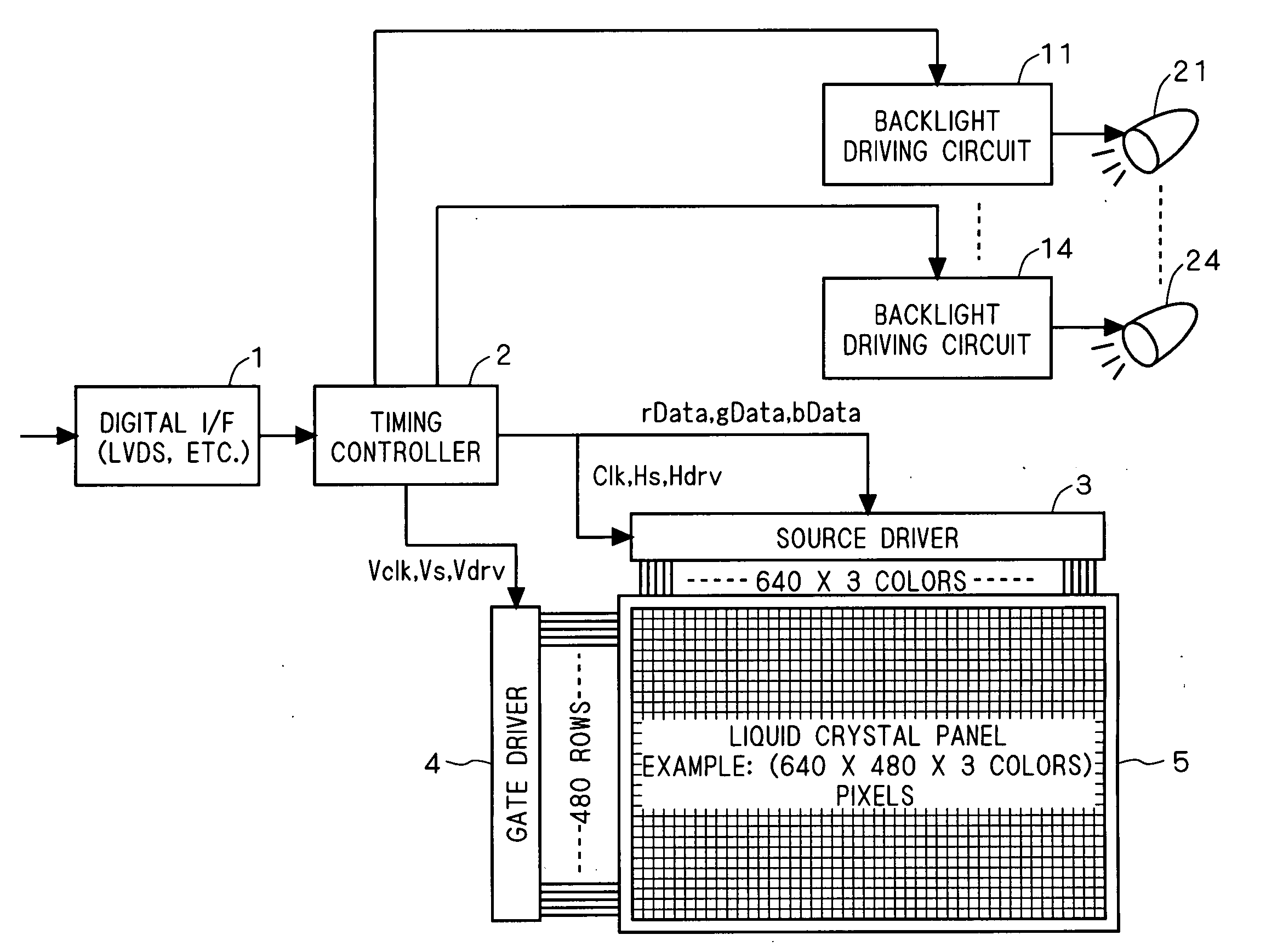
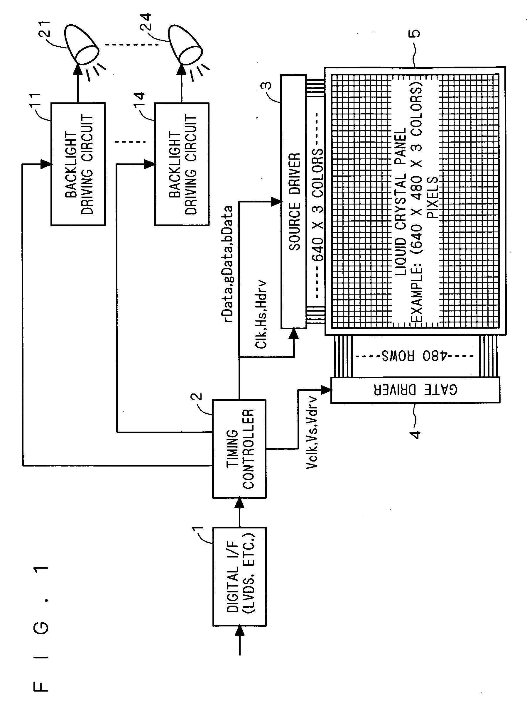
[0070]FIG. 1 is a block diagram of transmission type liquid crystal display device in a first embodiment of the present invention. This liquid crystal display device is a liquid crystal panel device having a display screen of pixel configuration of 640 columns×3 colors×480 rows.
[0071] The liquid crystal display device mainly includes a liquid crystal panel 5 having color pixels arrayed in matrix, a source driver (circuit) 3, a gate driver (circuit) 4, a timing controller (timing control unit) 2, a digital I / F (circuit) 1, backlight driving circuits 11 to 14, and divided backlights 21 to 24.
[0072] A digital signal sent from a digital IF circuit (low voltage differential signaling, LVDS, or the like) of television is received in a receiver of the digital I / F 1 (LVDS, or the like), and is put into the timing controller 2.
[0073] The timing controller 2 sends image data (analog image signal rData, analog image signal gData, analog image signal bData) to the sou...
second embodiment
(Entire Configuration)
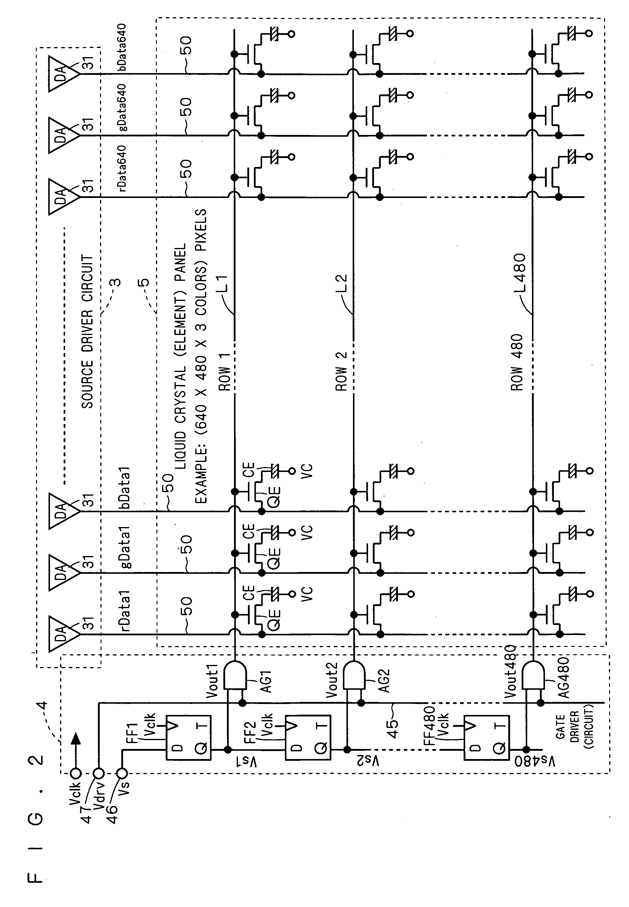
[0133] In the liquid crystal display device in a second embodiment, the entire configuration is same as in the first embodiment shown in FIG. 1 to FIG. 3.
(Structure of Backlight)
[0134]FIG. 10 is an explanatory diagram of backlight of liquid crystal display device in the second embodiment. As shown in the diagram, the transmission type liquid crystal panel 5 is composed of pixels of M columns×N rows same as in the first embodiment.
[0135] On the back side of the liquid crystal panel 5, a light guide plate 9 is adhered, and a reflector plate 7 is adhered to its back side. The light guide plate 9 diffuses, same as the light guide plate 8 in the first embodiment, the light from the side (right and left sides in FIG. 10) and guides to the side (front and rear sides) contacting with the liquid crystal module, and does not so reflect to the opposite side (vertical direction in this case) direction.
[0136] In the second embodiment, too, in the same manner as in th...
third embodiment
(Entire Configuration)
[0149] In the liquid crystal display device in a third embodiment, the entire configuration is same as in the first embodiment shown in FIG. 1 to FIG. 3.
(Structure of Backlight)
[0150]FIG. 12 is an explanatory diagram of backlight of liquid crystal display device in the third embodiment. As shown in the diagram, the transmission type liquid crystal panel 5 is composed of pixels of M columns×N rows same as in the first embodiment.
[0151] On the back side of the liquid crystal panel 5, a light guide plate 9 is adhered same as in the second embodiment, and a reflector plate 7 is adhered to its back side.
[0152] In the third embodiment, too, in the same manner as in the first embodiment, the liquid crystal panel 5 is divided into four divided regions DA1 to DA4, and corresponding to these divided regions DA1 to DA4, four ray emission light sources 21c to 24c formed of fluorescent lamps are disposed vertically each at both sides of light guide plate 9 (right and...
PUM
 Abstract
Description
Claims
Application Information
 - R&D
- Intellectual Property
- Life Sciences
- Materials
- Tech Scout
- Unparalleled Data Quality
- Higher Quality Content
- 60% Fewer Hallucinations
Browse by: Latest US Patents, China's latest patents, Technical Efficacy Thesaurus, Application Domain, Technology Topic, Popular Technical Reports.
© 2025 PatSnap. All rights reserved.Legal|Privacy policy|Modern Slavery Act Transparency Statement|Sitemap|About US| Contact US: help@patsnap.com


