Non-aqueous method for separating chemical constituents in spent nuclear reactor fuel

a nuclear reactor and chemical constituent technology, applied in the direction of nuclear elements, greenhouse gas reduction, uranium compounds, etc., can solve the problems of large volume of low-level liquid radioactive waste, the uncertainty of the net cost benefit of plutonium recovery, and the current low cost of gaseous diffusion operation

Inactive Publication Date: 2006-10-19
JANES CLARENCE W
View PDF11 Cites 22 Cited by
  • Summary
  • Abstract
  • Description
  • Claims
  • Application Information

AI Technical Summary

Benefits of technology

[0035] Another object of the present invention is to provide a method for extracting plutonium from spent nuclear reactor fuel for secure custody thereof by authorized personnel with low proliferation risk.

Problems solved by technology

The PUREX process requires a large central chemical facility equipped with expensive hot cells, extensive liquid storage and requires transport of the spent fuel from the security of the individual nuclear power plants.
A major drawback of the PUREX process is the production of large volumes of low level liquid radioactive wastes.
Additionally, the current low cost of gaseous diffusion operation needed and to buy and enrich the additional natural uranium outweighs the uncertain net cost benefit of the plutonium recovered.
It is agreed by many analysts that regardless of the single choice of the disposal site obtaining nationwide public acceptance will be difficult for the transportation of the spent fuel across the U.S. road and rail network.
This perception arises from considering normal transportation accident rates together with the potential for terrorist hijacking and the resulting liability.

Method used


Image

  • Non-aqueous method for separating chemical constituents in spent nuclear reactor fuel
  • Non-aqueous method for separating chemical constituents in spent nuclear reactor fuel
  • Non-aqueous method for separating chemical constituents in spent nuclear reactor fuel

Examples


Embodiment Construction

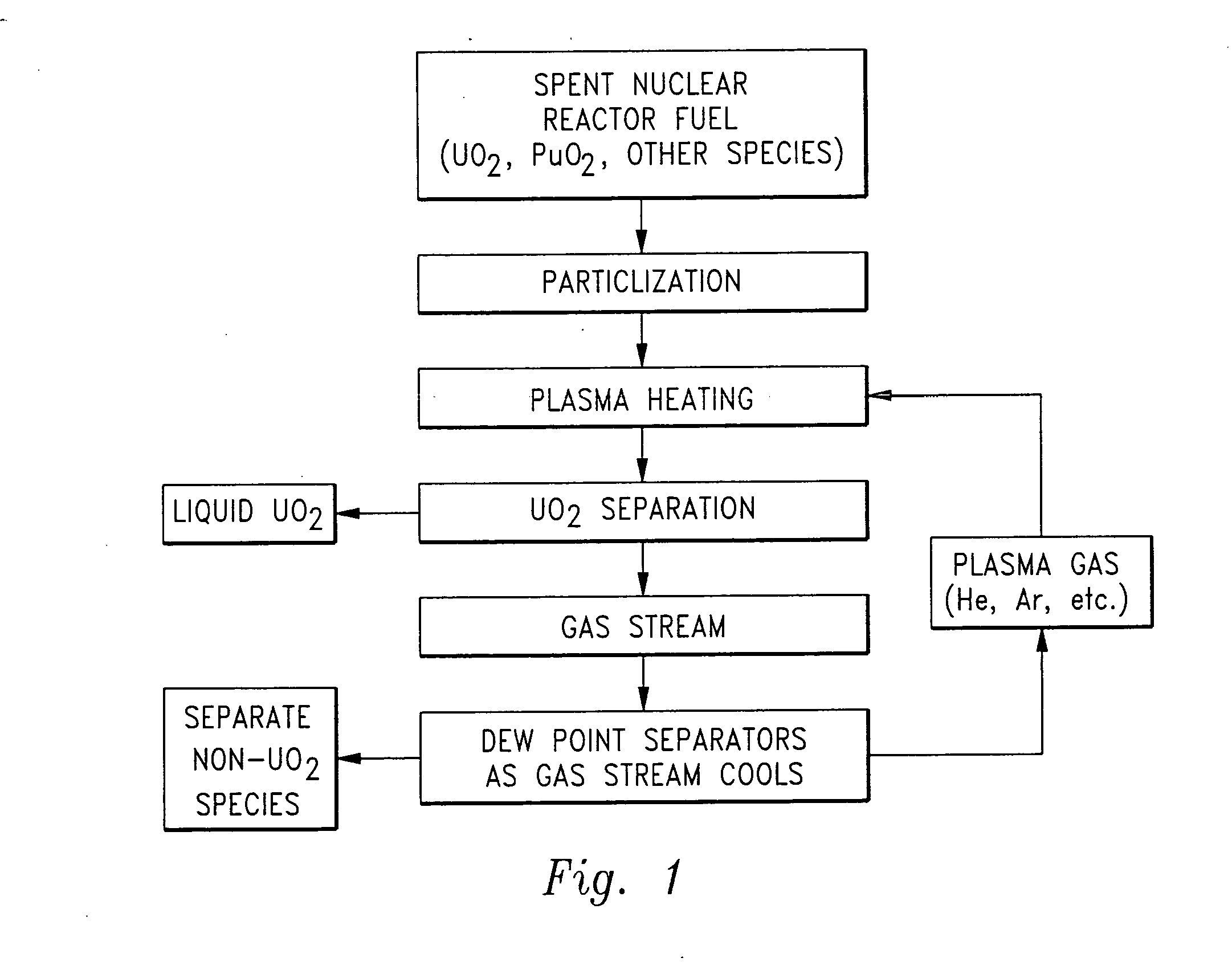
[0043] Referring to the drawings, wherein like reference numerals represent like parts throughout the various drawing figures, a non-aqueous method for separating chemical constituents in spent nuclear reactor fuel is described according to a preferred embodiment and various alternative embodiments. The spent nuclear reactor fuel F (FIG. 1) typically initially includes various isotopes of UO2 as well as transuranic chemical constituents (actinides) and fission products. Once the fuel F has been separated according to this invention, preferably each of the chemical constituents have been separated from each other without generation of any additional radioactive waste, and particularly no contaminated solvents or other liquid waste.

[0044] In essence, and with particular reference to FIG. 1, the basic steps in the separation method of this invention are described. The spent nuclear reactor fuel F is initially provided in the form of UO2, plutonium dioxide (PuO2) and various other chem...


PUM

PropertyMeasurementUnit
timeaaaaaaaaaa
boiling pointaaaaaaaaaa

Abstract

Herein is a method of segregating chemical species contained in spent nuclear reactor fuel without employing conventional acid dissolution. Particularly, pellets of spent fuel are ground to talc sized particles. Heat is added. The preferred heating is by flow through a plasma arc producing micron sized liquid drops suspended in helium flow. The vapor pressure of the chemical species is significantly greater than uranium dioxide. the ultra volatile chemical species evolve from the drops into the helium flow. The gas phase is separated from the mist by a gas/liquid separator (demister). Heavy mist drops of UO2 impact the walls, coalesce and flow down to the separator drain, becoming legally transportable. Helium flow exhausts from the separator vertically. The gaseous chemical species will condense in sequentially cooler stages and separate from the helium down to the cryogenic temperatures of liquid radioactive xenon and krypton. Non-condensed helium is recycled.

Description

FIELD OF THE INVENTION [0001] This invention pertains generally to reducing risk in the disposition of spent nuclear reactor fuel, and more particularly to the reduction of spent nuclear fuel into chemical constituents, achieving a physical separation of the radioactive elements from the inert, often valuable, non-radioactive or low level radioactive, transportable majority of the material. More particularly, this invention relates to unique separation methods and apparatuses which make use of the greater vapor pressures at elevated temperature of the chemical species generated from the many neutron interactions than that of the remaining unreacted spent uranium dioxide. BACKGROUND OF THE INVENTION [0002] From successful operation of the world's first nuclear reactor in December 1942 it was realized that an efficient separation process was urgently needed. Of primary importance at that time was collection of plutonium, produced by the neutron interaction with natural uranium U238. T...

Claims


Application Information

Patent Timeline
Patent Type & Authority Applications(United States)
IPC IPC(8): C01G56/00
CPCC01G43/025G21C19/48G21C19/44C01G56/005Y02W30/50Y02E30/30
Inventor JANES, CLARENCE W.
Owner JANES CLARENCE W
Why Eureka
Try Eureka