Bleaching device using electro-optical and chemical means, namely in the medical and dental field

a technology of electro-optical and chemical means, applied in the field of bleaching devices, can solve the problems of many limits, long application time, and immobilization of patients, and achieve the effect of fast penetration

Inactive Publication Date: 2006-10-19
DURET
View PDF16 Cites 49 Cited by
  • Summary
  • Abstract
  • Description
  • Claims
  • Application Information

AI Technical Summary

Benefits of technology

[0035] The purpose of the present invention is to solve the above-mentioned drawbacks by providing a complete bleaching unit made up of an electrochemical system, finding its application in particular in the dental and medical fields, allowing, thanks to the creation of an electrophoretic field, a strong, fast penetration and directing the bleaching agents, their removal under the same conditions together with the molecules responsible for coloration and an effective and controlled

Problems solved by technology

Unfortunately and very quickly, both the practitioners and their patients realized that: the application time was very long and required the immobilization of the patient during more than 5 minutes per tooth, or 20 minutes per half arch.
the cost of the intervention was therefore painful and prohibitive!
However this process, even if it reduced the time considerably, had many limits.
since the cost of these lamps is very high, the treatment remained relatively expensive, since these methods require high peroxide concentrations, they impeded their use by the patient at home, the thermal rise observed in the tooth was disproportionate compared to the activation of the product and could even be dangerous when the action was too long, it was impossible to properly control the thermal value at the very level of the tooth, to the risk of causing significant disorders in the health of dental pulp itself.
Moreover, the movement even of the hand could result into changes in localization of the point of luminous or thermal impact.
Moreover, at no time has been solved a fundamental problem which justified the putting under monitoring of the bleaching products and in particular the peroxide by all the safety committees in the field of health of the EC and the FDA, irrespective of the degree of degrada

Method used


Image

  • Bleaching device using electro-optical and chemical means, namely in the medical and dental field
  • Bleaching device using electro-optical and chemical means, namely in the medical and dental field
  • Bleaching device using electro-optical and chemical means, namely in the medical and dental field

Examples


Embodiment Construction

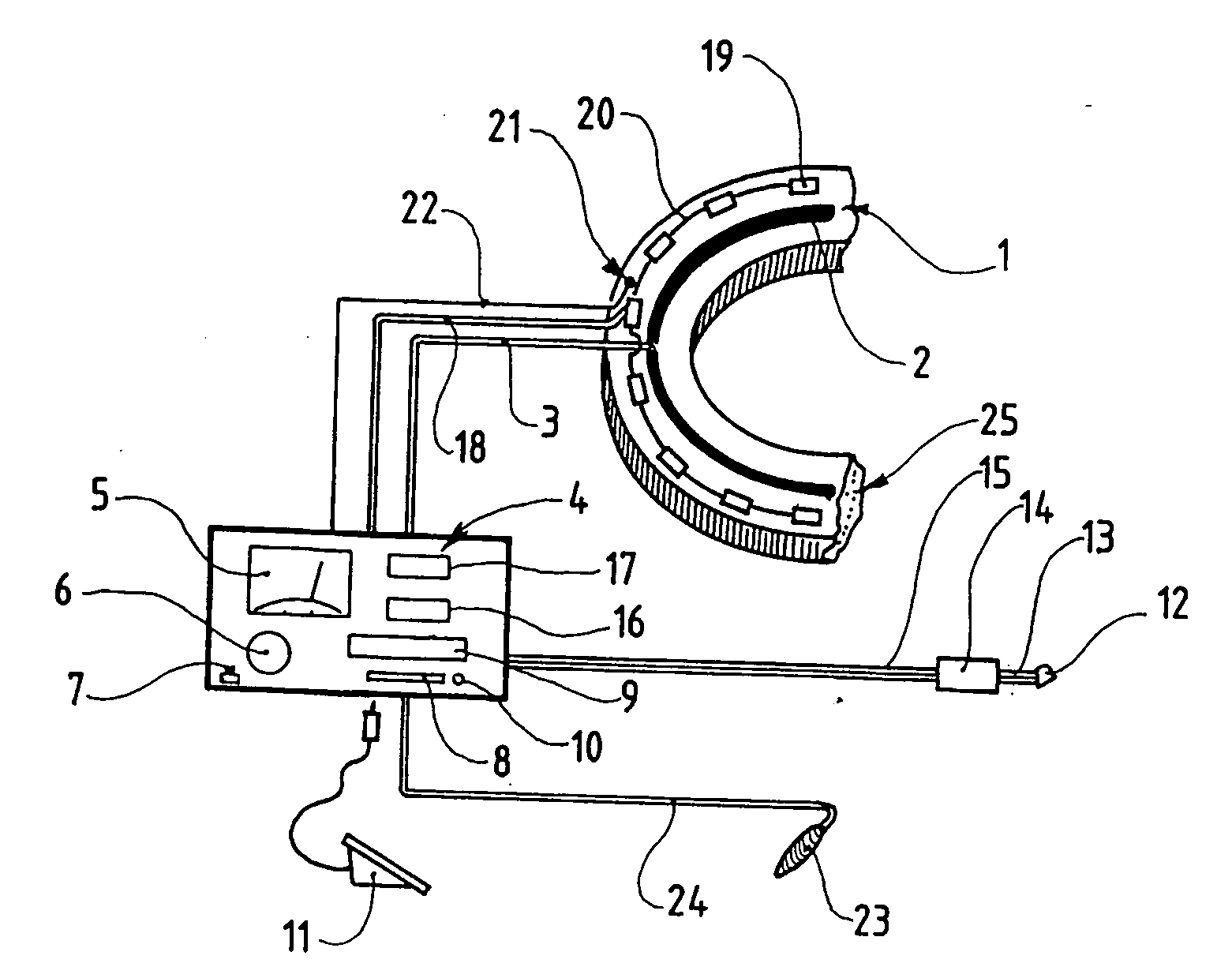
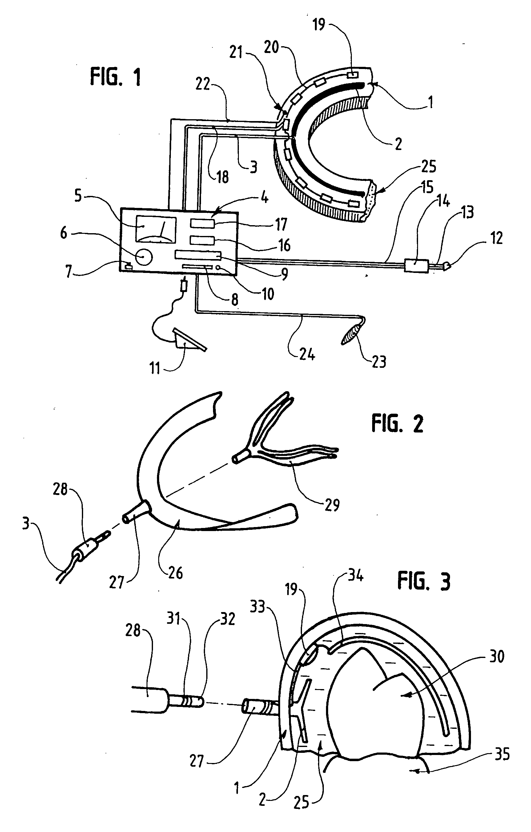
[0100] As shown in these figures, the present invention relates to a bleaching device which will be of particular interest in the dental field.

[0101] As can be seen in FIG. 1, this device includes a standard gutter 1 with its electrophoretic resistor 2 and an array of activating LEDs 19 connected through electric connections 3 to an electronic control, monitoring and storing box 4 and with reversed polarization handle 23.

[0102] The standard gutter 1, aimed at covering the dental arch to be bleached, is provided with a electric conduction system 2 allowing the creation of an electrophoretic field, accompanied by a thermal rise, having a positive or negative polarity, and which is connected, for example by an electric lead 3, with an adjusting and control unit 4 contained in a casing, allowing to define or program the parameters of the clinical treatment (time, degree wished by the patient) and those defining the electrophoretic field (intensity, voltage . . . ). These controllable ...


PUM


Abstract

A device for bleaching a part of the human body has a wave-current generator, a plurality of electrodes and a conductive gel. The conductive gel is maintained in contact with the part of the body. An active product is cooperative with the gel so as to be activated under the presence of light or heat. A conductive circuit and a resistor define poles of the electrodes on the container of the conductive gel and the part of the body. The photosensitive bleaching product is activated by applying photonic energy of a wavelength of 400 to 500 nanometers.

Description

RELATED U.S. APPLICATIONS [0001] Not applicable. STATEMENT REGARDING FEDERALLY SPONSORED RESEARCH OR DEVELOPMENT [0002] Not applicable. REFERENCE TO MICROFICHE APPENDIX [0003] Not applicable. FIELD OF THE INVENTION [0004] The present invention relates to a device for bleaching bodies ensuring their structural integrity, applicable in particular in the industrial fields for fabrics, the medical field for nails and hairs and the dental field for teeth, comprising an electrophoretic-field creator taking, directly or through an electrically active product, the active bleaching molecules towards their targets, the degraded products or those not responsible for coloration towards the outside and eventually one or several active molecules capable of reconstituting the body having been subjected to the action of the bleaching products in the body, thus decreasing any degradation in the short or medium run which could be caused by the chemical applications of the active products and the remo...

Claims


Application Information

Patent Timeline
IPC IPC(8): A61C5/00
CPCA45D29/00A45D2019/0066A61C1/0015A61C19/066A61C19/04A61C19/06A61C19/003A45D19/0066
Inventor DURET, FRANCOIS
Owner DURET
Why Eureka
Try Eureka