Advanced body armor utilizing shear thickening fluids

a technology of body armor and thickening fluid, which is applied in the direction of knitting, weaving, straight-bar knitting machines, etc., can solve the problems of limited chest and head protection, significant percentage of battlefield injuries to the extremities, and limited body armor, so as to achieve high modulus, not impede fabric flexibility, and high strength

Inactive Publication Date: 2006-10-19
UNIVERSITY OF DELAWARE
View PDF25 Cites 59 Cited by
  • Summary
  • Abstract
  • Description
  • Claims
  • Application Information

AI Technical Summary

Benefits of technology

[0015] It is a feature of the present invention to provide a fabric and articles formed therefrom comprising high strength, high modulus polymeric fibers or yarns impregnated with a fluid that exhibits shear thickening properties, herein referred to as a “shear thickening fluid” (or “STF”). The STF remains flowable after impregnation, so as to not impede fabric flexibility, but modifies the coefficient of friction between the fibers or yarns by rigidizing during an impact event.

Problems solved by technology

Currently, body armor is fielded only in specific high-risk scenarios, and is typically limited to chest and head protection.
However, a significant percentage of battlefield injuries occur to the extremities, including arms, legs, hands, and neck.
These materials are too bulky and stiff for application in extremities protection.
This shear thickening phenomenon can damage processing equipment and induce dramatic changes in suspension microstructure, such as particle aggregation, which results in poor fluid and coating qualities.
Such fibers, when formed into a fabric network, exhibit poor energy transfer to neighboring fibers during an impact event.
This lack of energy transfer may correlate to a reduced efficiency in dissipating the kinetic energy of a moving object thereby necessitating the use of more material to achieve full dissipation.
The increase in material is typically achieved through the addition of more layers of material which has the negative consequence of adding to the bulk and weight of the overall fabric structure.
Furthermore, economic considerations dictate that the number of fabric layers utilized for this purpose cannot be excessive.
Several techniques are known for increasing the energy transfer properties between fibers or yarns but each of these known techniques has certain inherent deficiencies.
However, such roughening is believed to have limited utility due to the resultant degradation in the fiber.
One deficiency in this practice is the formation of fiber-to-fiber bonds.
Such bonding may result in stress reflections at yarn crossovers during impact by a moving article, which cannot be transferred away from the impact region.
Another deficiency is the large weight gain typical of coatings, which may be ten percent or more.
A further limitation of this approach is a significant decrease in fabric flexibility due to the addition of the relatively stiff polymer coating.
A related method is to use a sticky resin that creates adhesion between the fibers, as disclosed in U.S. Pat. No. 1,213,118 to Lynch, but this technique has the same inherent deficiencies of fiber to fiber bonding and increased weight as exhibited by coatings.
However, these relatively high friction fibers may reduce the overall fabric strength.
However, the necessity of a cellular containment structure results in a material system which is bulky, heavy, and relatively inflexible.

Method used


Image

  • Advanced body armor utilizing shear thickening fluids

Examples


example 1

Ballistic Performance

[0032] In the following examples silica particles (Nissan Chemicals MP4540) were suspended in ethylene glycol, at a volume fraction of approximately 0.57. The average particle diameter, as measured using dynamic light scattering, was determined to be 446 nm. Rheological measurements have shown that this STF undergoes a shear thickening transition at a shear rate of approximately 102-103 s−1. Additionally, this transition is reversible, i.e. this liquid-to-solid transition induced by flow is not associated with particle aggregation, nor does it result in any irreversible change in the dispersion. Full details regarding the preparation and rheological properties of the STF can be found in Lee et al., J. Mat. Sci., 2002 and Lee and Wagner Rheol. Acta., 2002.

[0033] The Kevlar® fabric used in all composite target constructions was 600 denier plain-woven Hexcel-Schwebel high performance fabric Style 706 composed of Kevlar® KM-2 aramid fibers (poly-paraphenylene tere...

example 2

Stab Performance

[0053] In the following examples silica particles (Nippon Shokubai Seahostar KE-P50) were suspended in polyethylene glycol, at a volume fraction of approximately 0.52. The average particle diameter, as measured using dynamic light scattering, was determined to be 450 nm. The Kevlar fabric used was 600 denier plain-woven Hexcel-Schwebel high performance fabric Style 706 composed of Kevlar® KM-2 aramid fibers (poly-paraphenylene terephthalamide) with an areal density of 180 g / m2.

[0054] Two targets are compared: 15 layers of neat Kevlar fabric, with an areal density of 2670 g / m2, and 12 layers of STF-Kevlar, with an areal density of 2650 g / m2. The STF-Kevlar sample was prepared according to the methods in Example 1. Note that both targets have comparable areal densities. The neat Kevlar sample is approximately 25.4 cm×35.6 cm, while the STF-Kevlar sample is approximately 50.8 cm×35.6 cm.

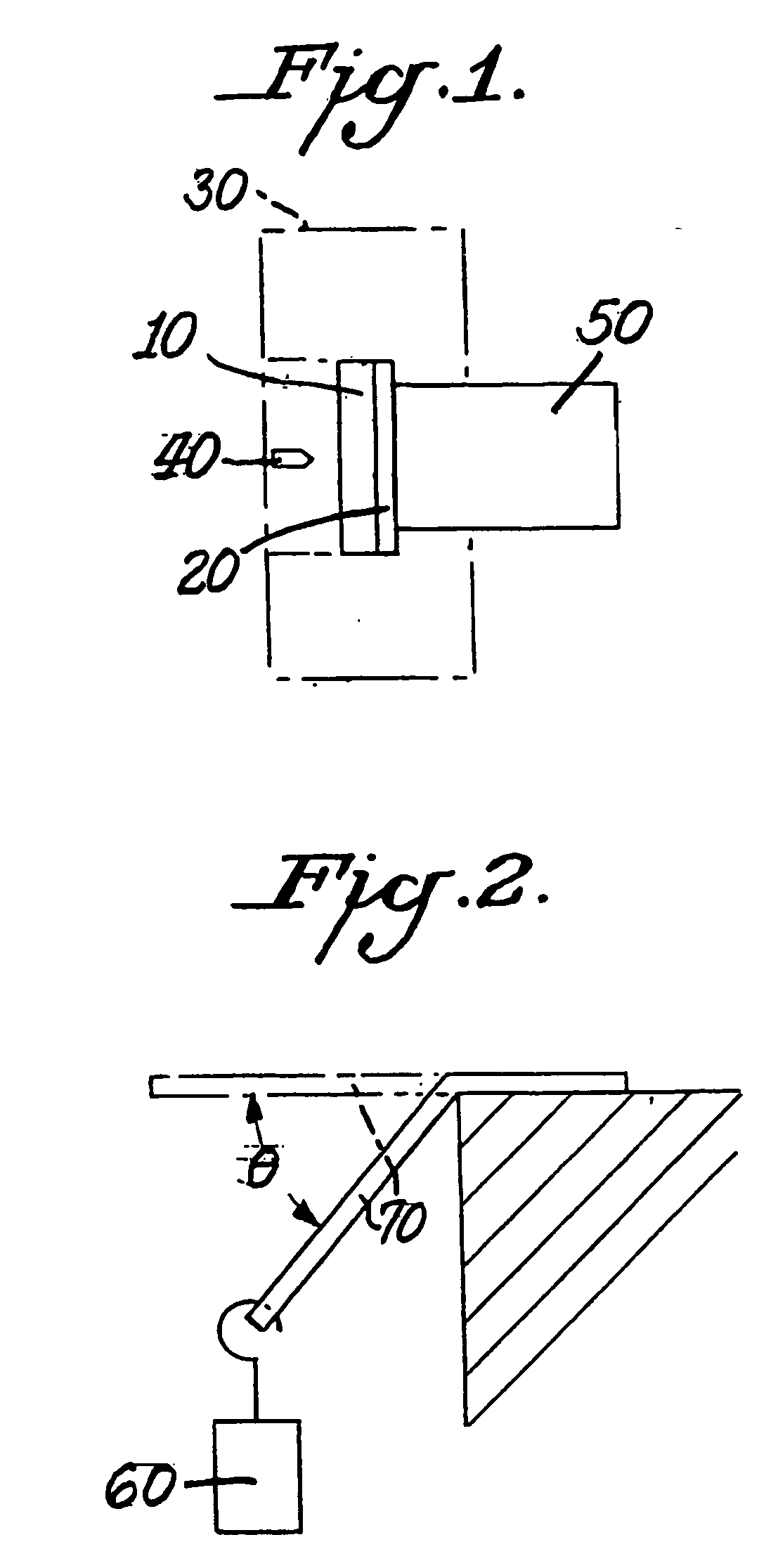
[0055] Stab resistance measurements were performed using an end effector fabricat...


PUM

PropertyMeasurementUnit
diameter sizeaaaaaaaaaa
sizeaaaaaaaaaa

Abstract

An armor composite material has been invented which contains a fabric which has been impregnated with shear thickening fluid. This invention offers a ballistic resistant material that is more flexible and less bulky than comparable, conventional ballistic fabric. The material in the alternative can be puncture resistant. The invented material offers superior ballistic performance and / or puncture resistance compared to conventional ballistic fabric-based materials of equal thickness. The invented material can be applied to applications requiring armor that is compact and / or flexible, such as body armor, protective clothing and flexible protective devices and shields, and stab resistant clothing and devices.

Description

GOVERNMENT LICENSE RIGHTS [0001] The United States Government has rights in this invention as provided for by Army Research Laboratories, CMR contract nos. DAAD19-01-2-0001 and DAAD19-01-2-0005.BACKGROUND OF THE INVENTION [0002] Body armor is essential equipment for police and military. Currently, body armor is fielded only in specific high-risk scenarios, and is typically limited to chest and head protection. However, a significant percentage of battlefield injuries occur to the extremities, including arms, legs, hands, and neck. Armor for these extremities must offer protection from fragment and ballistic threats, without significantly limiting soldier mobility and dexterity. [0003] Conventional body armor materials are typically comprised of many layers of polyaramid poly(phenylene diamine terephthalamide) fabric, sold by DuPont under the registered name of Kevlar®, with optional ceramic tile inserts. These materials are too bulky and stiff for application in extremities protecti...

Claims


Application Information

Patent Timeline
Patent Type & Authority Applications(United States)
IPC IPC(8): B32B27/04B32B27/02B32B5/02D02G3/40D06M23/08F41H5/04
CPCA41D31/0061F41H5/0485B32B5/024B32B5/026B32B5/26B32B5/28B32B2250/20B32B2260/023B32B2260/04B32B2260/046B32B2262/0261B32B2262/0269B32B2262/101B32B2262/106B32B2264/0235B32B2264/025B32B2264/102B32B2264/104B32B2264/12B32B2307/3065B32B2307/536B32B2307/54B32B2307/542B32B2307/546B32B2307/558B32B2307/56B32B2413/00B32B2437/00B32B2459/00B32B2509/00B32B2571/02B32B2581/00D02G3/40D06M11/76D06M11/79D06M23/08F41H5/0471B32B5/022A41D31/245Y10T442/20Y10T442/2361Y10T442/2902Y10T442/273Y10T442/40Y10T442/3707Y10T442/2893Y10T442/2992Y10T442/2738Y10T442/3472Y10T442/659Y10T442/2615Y10T442/2984Y10T442/2311Y10T442/2861Y10T442/2623
Inventor WAGNER, NORMANWETZEL, ERIC D.
Owner UNIVERSITY OF DELAWARE
Why Eureka
Try Eureka