Optical thin film for solar cells and method of forming the same

a technology of solar cells and optical thin films, which is applied in the direction of electrical equipment, semiconductor/solid-state device manufacturing, and semiconductor devices. it can solve the problems of inability to apply the cover glass directly to the thin-film solar cell in terms of weight and flexibility, and the conventional cover glass has a problem about the increase in the weight of the solar cell, etc., and achieve the effect of adequate thermal radiative characteristics

Inactive Publication Date: 2006-11-02
JAPAN AEROSPACE EXPLORATION AGENCY
View PDF5 Cites 9 Cited by
  • Summary
  • Abstract
  • Description
  • Claims
  • Application Information

AI Technical Summary

Benefits of technology

[0027] The optical thin film of the present invention can be laminated on a surface of a solar cell to provide adequate thermal radiative characteristics (solar absorptivity and infrared ...

Problems solved by technology

While the conventional cover glass can achieve adequate thermal radiative and optical characteristics in a specific type of space solar cell, such as a crystal-based solar cell, it is inappropriate to appl...

Method used


Image

  • Optical thin film for solar cells and method of forming the same
  • Optical thin film for solar cells and method of forming the same
  • Optical thin film for solar cells and method of forming the same

Examples


Embodiment Construction

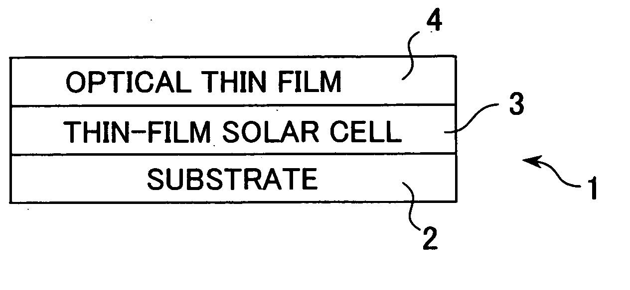
[0034] With reference to the drawings, one embodiment of the present invention will now be described. FIGS. 5 and 6 are schematic sectional views showing two conventional solar cell structures 30, 40. FIG. 1 is a schematic sectional view showing a solar cell structure 1 incorporating an optical thin film according to one embodiment of the present invention. As seen in FIGS. 5 and 6, each of the conventional solar cell structures 30, 40 includes a thick cover glass layer (32, 42) for protecting a crystal solar cell (31, 41). This cover glass layer (32, 42) is attached on the crystal solar cell (31, 41) using an adhesive. In the conventional solar cell structure 30 illustrated in FIG. 5, the cover glass layer 32 is directly attached on a top surface of the crystal solar cell 31, and an antireflection coating 33 is formed on an upper surface of the cover glass layer 32. In the conventional solar cell structure 40 illustrated in FIG. 6, the cover glass layer 42 is attached relative to a...


PUM


Abstract

Disclosed is an optical thin film for a thin-film solar cell, which is formed directly on a top surface of the thin-film solar cell having a transparent conductive film layer to provide a high infrared emissivity and a lower solar absorptivity to the thin-film solar cell. The optical thin film is formed through a vacuum vapor deposition process. The thin film makes it possible to provide enhanced infrared emissivity based on its reduced thickness, while suppressing unnecessary incoming solar radiation in a simplified structure to achieve a reduced solar absorptivity so as to maintain desired cell efficiency. The optical thin film of the present invention is capable of achieving reduction in weight of a solar cell, and suitable for use, particularly, in space environments.

Description

TECHNICAL FIELD [0001] The present invention relates to a technique of an optical thin film for thin-film solar cells, for allowing an on-ground thin-film solar cell with a top layer formed of a transparent conductive film to have improved thermal radiative and optical characteristics suitable for use in space environments. BACKGROUND ART [0002] In a crystal-based solar cell for use in space, a cover glass using borosilicate glass as a base material and having a high infrared emissivity is attached thereonto. Based on the high emissivity, the cover glass serves as means for releasing heat from a surface of the glass to outer space. In space applications of a thin-film solar cell which has been originally developed for use on the ground, if the conventional space cover glass is used therein, advantages of the thin-film solar cell will be spoiled in terms of weight and flexibility. Differently from the crystal-based solar cell, most of the thin-film solar cells have a top layer formed...

Claims


Application Information

Patent Timeline
IPC IPC(8): H01L31/00
CPCH01L31/02167Y02E10/50H01L31/02168
Inventor SHIMAZAKI, KAZUNORI
Owner JAPAN AEROSPACE EXPLORATION AGENCY
Why Eureka
Try Eureka