Systems and Methods for Utilization of Waste Heat for Sludge Treatment and Energy Generation

a technology of waste heat and sludge treatment, applied in the direction of energy input, energy based wastewater treatment, drying machines, etc., can solve the problems of significant disposal problems, nuclear power plants and other heat-producing facilities or processes,

Inactive Publication Date: 2006-11-02
WINTERBROOK INVESTMENT PARTNERS
View PDF13 Cites 15 Cited by
  • Summary
  • Abstract
  • Description
  • Claims
  • Application Information

AI Technical Summary

Problems solved by technology

Historically, natural gas, geo-thermal, and nuclear power plants and other heat-producing facilities or processes (such as the production of paper or pulp) have struggled to dispose of waste heat generated by their production processes.
To avoid the build up of salts and other impurities in the process water, a large percentage of this water must be replaced on a daily basis creating significant disposal issues.
The United States Environmental Protection Agency (EPA) and various other state environmental quality agencies have set limits on wastewater temperatures, requiring most large heat-producing facilities to build large pumping and cooling tower systems that are extremely expensive to operate.
Additionally, the disposal of organic sewage sludge poses a significant problem for most industrial and municipal wastewater facilities.
Facilities with limited space or humid environments, however, are forced to dispose of sludge in its dewatered condition, or resort to extremely energy-intensive final drying techniques such as, without limitation, those employing direct and indirect drum dryers.
The cost of final drying in these cases is typically prohibitive, forcing the disposal of de-watered sludge in landfills or on certain acceptable agricultural crops or grazing fields.
In recent years the disposal of de-watered sludge in the above described manners has proven ecologically sensitive.
While short term disposal can have a positive effect on crop production, heavy metals and other contaminants in the material make long term disposal problematic, not to mention aesthetically disagreeable in certain areas.
One limiting factor of TSP technologies that remains is that the incoming sludge must have a low (for example, less than 10%) water content.
Because most facilities cannot dry the incoming sludge to this level onsite, expensive and energy-inefficient equipment must be located alongside the TSP equipment to dry incoming de-watered sludge before it is thermally processed.
In that case, however, less fuel or gas is available to generate energy at the end of the process, reducing the overall efficiency of the system.

Method used


Image

  • Systems and Methods for Utilization of Waste Heat for Sludge Treatment and Energy Generation
  • Systems and Methods for Utilization of Waste Heat for Sludge Treatment and Energy Generation
  • Systems and Methods for Utilization of Waste Heat for Sludge Treatment and Energy Generation

Examples


Embodiment Construction

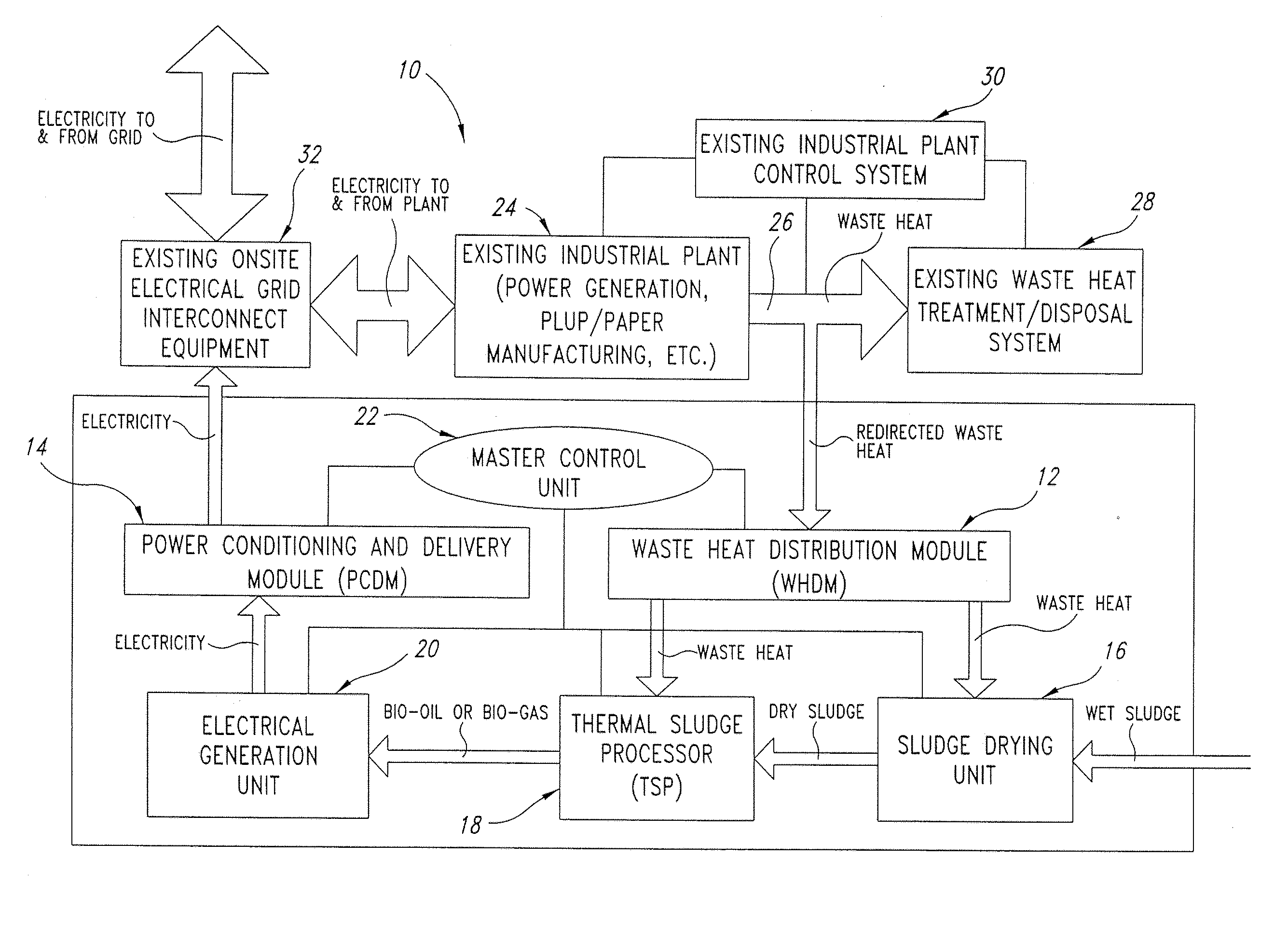
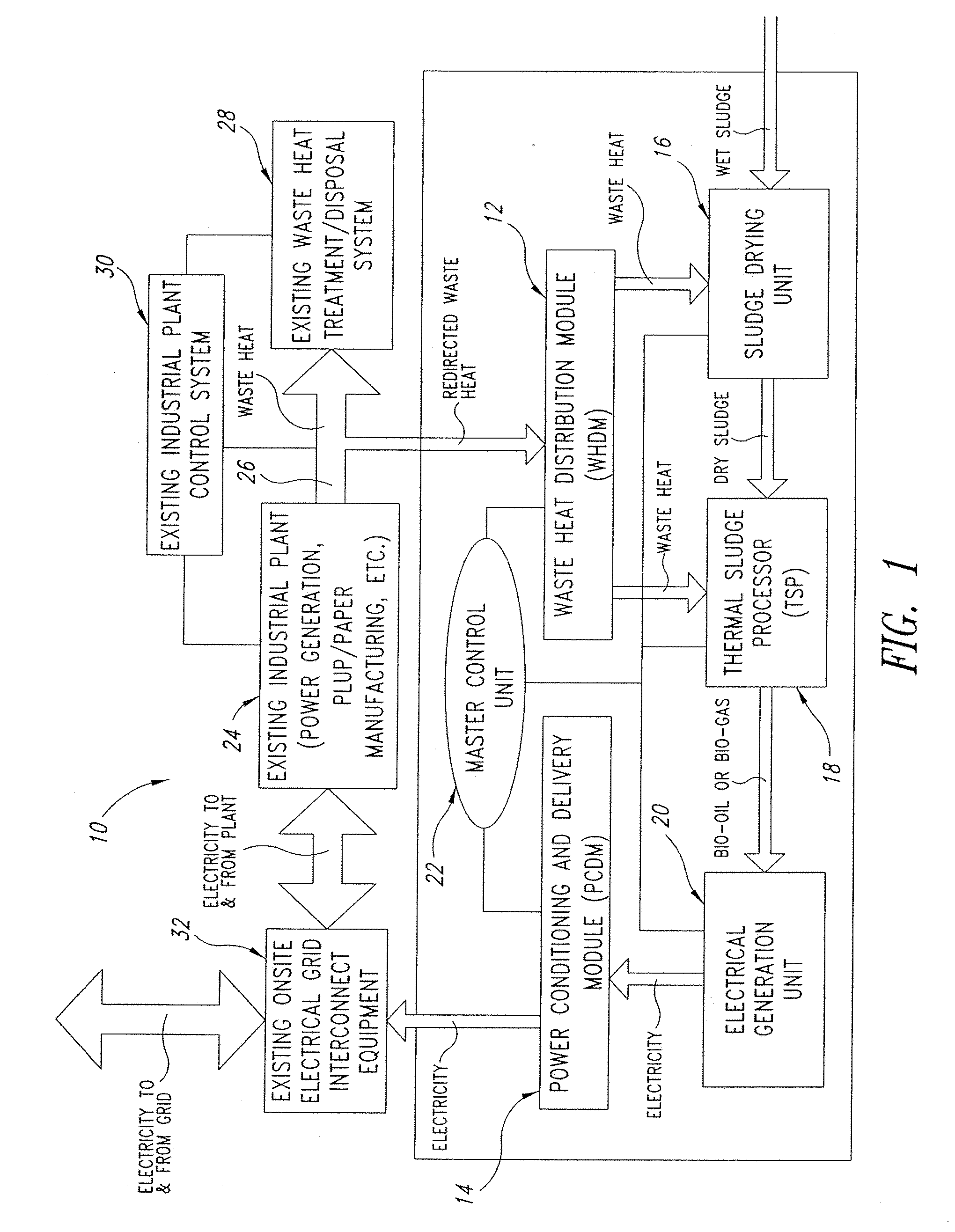
[0031] Many facilities generate waste heat that can be harmful to the environment if not properly treated before disposal. A number of processes requiring energy could benefit from the use of such waste heat. The disclosed embodiments according to the present invention provide a combination of systems and methods to efficiently dry sludge and / or to generate energy from sludge using waste heat. In one embodiment, as shown in FIG. 1, a system 10 or method for utilizing waste heat to dry sludge and generate energy includes a Waste Heat Distribution Module (WHDM) 12, a Power Conditioning and Delivery Module (PCDM) 14, a Sludge Drying Unit (SDU) 16, a Thermal Sludge Processor (TSP) 18 and an Electrical Generation Unit (EGU) 20. All of the above devices can be integrated via a Master Control Unit (MCU) 22 into a single process designed to safely dispose of waste heat and dry de-watered sludge while generating surplus energy.

[0032] In one embodiment according to the present invention, an ...


PUM

PropertyMeasurementUnit
electric poweraaaaaaaaaa
heataaaaaaaaaa
poweraaaaaaaaaa

Abstract

Disclosed systems and methods utilize waste heat from heat-producing facilities or processes to dry sludge. Disclosed systems and methods also utilize waste heat from heat-producing facilities or processes in the conversion of sludge into energy and energy products.

Description

CROSS REFERENCES TO RELATED APPLICATIONS [0001] The present application claims the benefit, under 35 U.S.C. § 119, of U.S. Provisional Patent Application Ser. No. 60 / 675,511, filed Apr. 27, 2005, and U.S. Provisional Patent Application Ser. No. 60 / 692,099, filed Jun. 20, 2005, the contents of which are incorporated herein by reference.FIELD OF THE INVENTION [0002] The present invention pertains to the utilization of waste heat from heat-producing processes to dry sludge. The present invention also pertains to the utilization of waste heat from heat-producing processes in the conversion of sludge into energy and energy products. BACKGROUND OF THE INVENTION [0003] Historically, natural gas, geo-thermal, and nuclear power plants and other heat-producing facilities or processes (such as the production of paper or pulp) have struggled to dispose of waste heat generated by their production processes. For example, natural gas is typically combusted in large turbine engines to generate powe...

Claims


Application Information

Patent Timeline
Patent Type & Authority Applications(United States)
IPC IPC(8): C02F1/02C02F11/13
CPCB09B3/00B09B3/0083C02F11/10C02F11/12C05F7/00Y02E50/343F26B23/001F26B2200/18Y02E50/10Y02E50/30C10L5/46Y02W10/40Y02W10/37Y02P20/129Y02A40/20Y02P70/10Y02W30/40C02F11/13B09B3/40
Inventor SHAIN, MARTIN J.PHILLIPS, RODGER W.
Owner WINTERBROOK INVESTMENT PARTNERS
Why Eureka
Try Eureka