Apparatus and method for controlling operation of reciprocating compressor

a reciprocating compressor and apparatus technology, applied in the field of apparatus and methods for controlling the operation of reciprocating compressors, can solve the problems of error generation, and severe distortion of the current applied to the motor of the reciprocating compressor. to achieve the effect of preventing current distortion

Inactive Publication Date: 2006-11-09
LG ELECTRONICS INC
View PDF17 Cites 56 Cited by
  • Summary
  • Abstract
  • Description
  • Claims
  • Application Information

AI Technical Summary

Benefits of technology

[0022] Therefore, one object of the present invention is to provide an apparatus and method for controlling the operation of a reciprocating compressor capable of preventing distortion of a current applied to the reciprocating compressor by generating a current amplitude value for compensating a difference value between a stroke reference value of the reciprocating compressor and a stroke estimate value and outputting the current amplitude value in a form of a sine wave to the reciprocating compressor.
[0023] Another object of the present invention is to provide an apparatus and method for controlling an operation of a reciprocating compressor capable of precisely detecting a mechanical resonance frequency of the reciprocating compressor based on a value of a current applied to the reciprocating compressor and a stroke estimate value by preventing distortion of the current applied to the reciprocating compressor.
[0024] Still another object of the present invention is to provide an apparatus and method for controlling an operation of a reciprocating compressor capable of degradation of efficiency due to a harmonic component of a current applied to the reciprocating compressor by preventing distortion of the current applied to the reciprocating compressor.

Problems solved by technology

As shown in FIG. 2, when the voltage inputted to the apparatus for controlling the operation of the reciprocating compressor is low or when a load is changed, the waveform of the current applied to the motor of the reciprocating compressor is severely distorted.
For example, the conventional apparatus for controlling the operation of the reciprocating compressor controls the voltage applied to the reciprocating compressor and does not control the waveform of the current passing through the reciprocating compressor.
Therefore, when the voltage inputted to the apparatus for controlling the operation of the reciprocating compressor is low or when a load is changed, the waveform of the current applied to the motor of the reciprocating compressor is severely distorted.
In addition, since the waveform of the current applied to the motor of the reciprocating compressor is not a sine wave (because the current waveform is distorted), when the mechanical resonance frequency of the reciprocating compressor is detected based on the value of the current applied to the reciprocating compressor and the stroke estimate value, an error is generated and efficiency of the reciprocating compressor is degraded due to a harmonic component of the current applied to the reciprocating compressor.
As mentioned above, the conventional apparatus for controlling the operation of the reciprocating compressor has the following problems.
That is, when the voltage in putted to the apparatus for controlling the operation of the reciprocating compressor is low or when a load is changed, the waveform of the current applied to the motor of the reciprocating compressor is severely distorted.
Accordingly, when the mechanical resonance frequency of the reciprocating compressor is detected based on the value of the current applied to the reciprocating compressor and the stroke estimate value, an error is generated and efficiency of the reciprocating compressor is degraded due to a harmonic component of the current applied to the reciprocating compressor.

Method used


Image

  • Apparatus and method for controlling operation of reciprocating compressor
  • Apparatus and method for controlling operation of reciprocating compressor
  • Apparatus and method for controlling operation of reciprocating compressor

Examples


Embodiment Construction

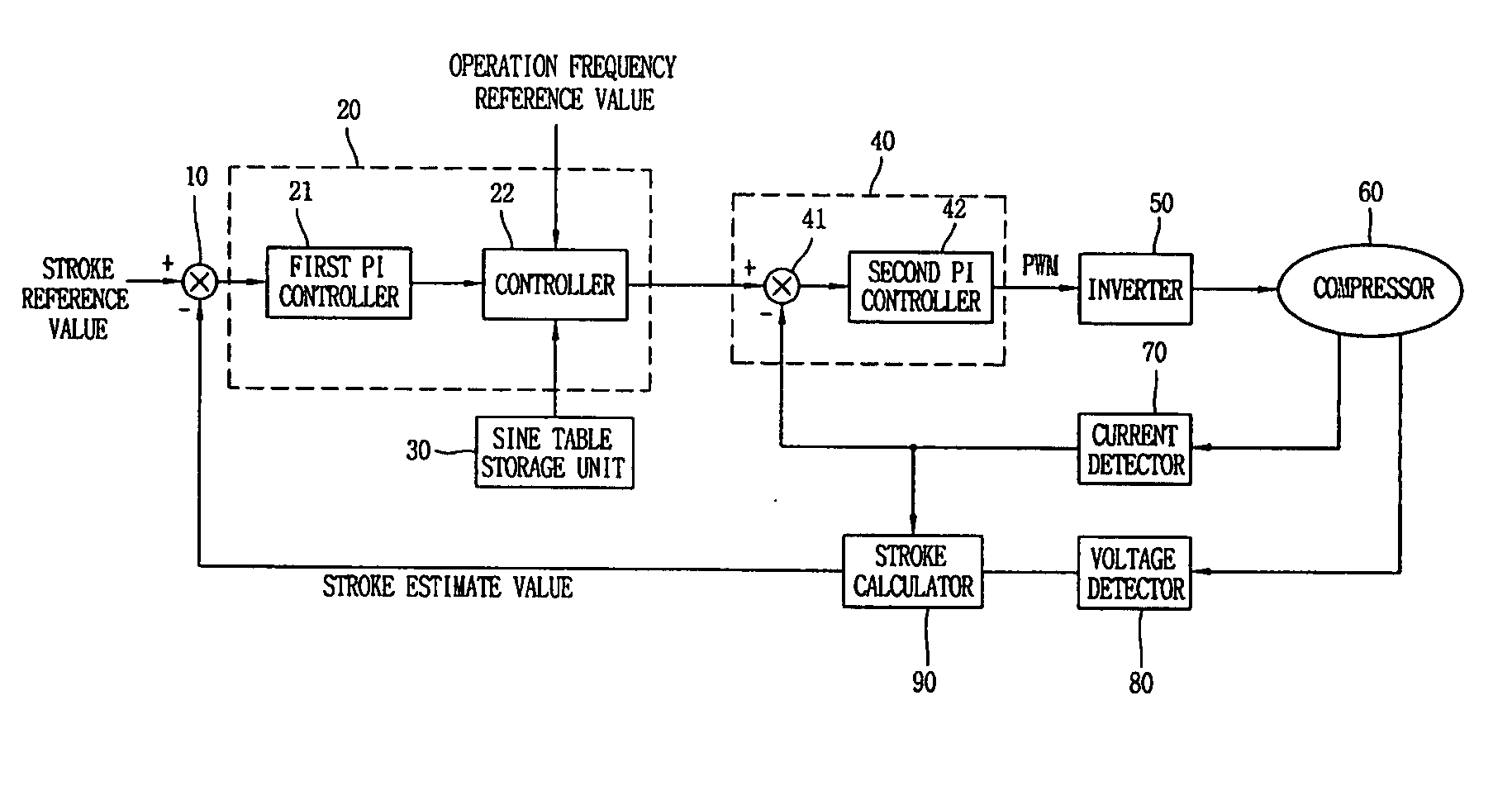
[0038] The apparatus and method for controlling the operation of a reciprocating compressor capable of preventing distortion of a current applied to the reciprocating compressor by generating a current amplitude value for compensating a difference value between a stroke reference value of the reciprocating compressor and a stroke estimate value and outputting the current amplitude value in a form of a sine wave to the reciprocating compressor in accordance with the present invention will be described with reference to FIGS. 3 to 5.

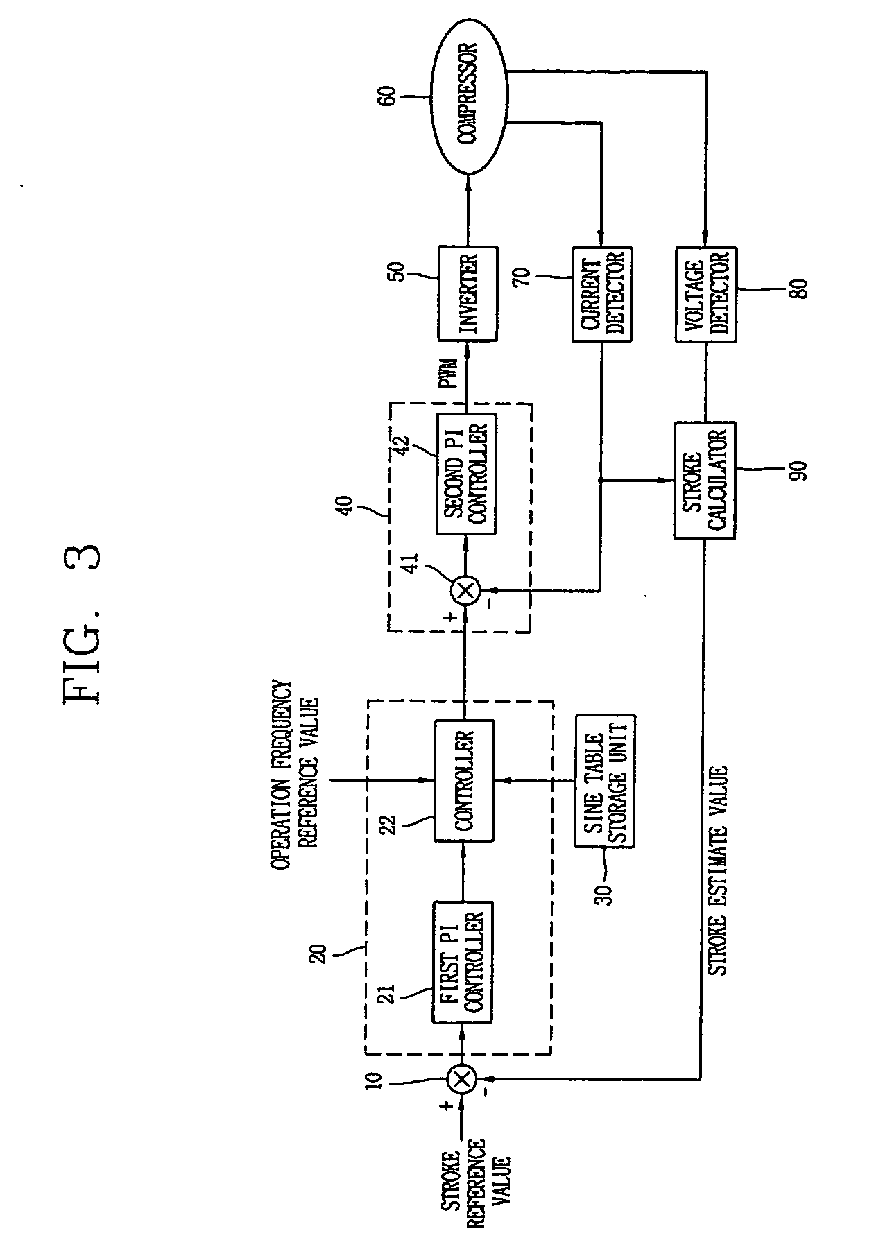
[0039]FIG. 3 is a block diagram showing an apparatus for controlling an operation of a reciprocating compressor in accordance with the present invention. As shown in FIG. 3, the apparatus for controlling an operation of a reciprocating compressor includes a current detector 70 for detecting a current applied to a motor of a reciprocating compressor 60; a voltage detector 80 for detecting a voltage applied to the motor; a stroke calculator 90 for calculati...


PUM


Abstract

An apparatus and method for controlling the operation of a reciprocating compressor are capable of preventing distortion of a current applied to the reciprocating compressor by generating a current amplitude value for compensating a difference value between a stroke reference value of the reciprocating compressor and a stroke estimate value and outputting the current amplitude value in a form of a sine wave to the reciprocating compressor. The apparatus for controlling an operation of a reciprocating compressor generates a current amplitude value for compensating a difference value between a stroke reference value and a stroke estimate value of the reciprocating compressor and outputs the current amplitude value in a sine wave form to the reciprocating compressor.

Description

BACKGROUND OF THE INVENTION [0001] 1. Field of the Invention [0002] The present invention relates to a compressor and, more particularly, to an apparatus and method for controlling an operation of a reciprocating compressor. [0003] 2. Description of the Prior Art [0004] In general, a reciprocating compressor (hereinafter, for simplicity, referred to as “reciprocating motor compressor”), which is operated by a linearly reciprocating electric motor without a crank shaft for converting a rotational motion to a linear motion, has less friction loss, and thus, can provide a higher compression efficiency than other compressors. [0005] When the reciprocating motor compressor is used for a refrigerator or an air-conditioner, a compression ratio of the compressor can be varied to control the cooling capacity by varying a stroke voltage applied to the reciprocating motor of the compressor. [0006] The conventional controlling of a reciprocating motor compressor will now be described with refer...

Claims


Application Information

Patent Timeline
Patent Type & Authority Applications(United States)
IPC IPC(8): F04B49/06
CPCF04B35/045F04B49/065H02P25/027F04B2203/0401F04B2201/0206H02P25/032F04B49/06F04B49/12F04B35/04F04B2203/0402F04B2207/046F04B2203/0404
Inventor LEE, CHEL WOONGSUNG, JI-WON
Owner LG ELECTRONICS INC
Why Eureka
Try Eureka