Exhaust aftertreatment device

an exhaust gas and aftertreatment technology, which is applied in the direction of machines/engines, mechanical equipment, separation processes, etc., can solve the problems of significant degradation of diesel fuel economy, high concentration of nox passing through the scr unreacted, and the extremely low nox emission level of gasoline engines with three-cylinder engines, etc., to achieve the effect of superior control of nox

Inactive Publication Date: 2006-11-09
FORD GLOBAL TECH LLC
View PDF15 Cites 25 Cited by
  • Summary
  • Abstract
  • Description
  • Claims
  • Application Information

AI Technical Summary

Benefits of technology

[0008] A SCR according to the present invention provides superior control of NOx during transient operating conditions compared to prior art SCRs when equipped on a diesel vehicle (FIGS. 7 and 8). The NOx breakthrough during transie

Problems solved by technology

Achieving low NOx (NO, nitric oxide, plus NO2, nitrogen dioxide) emissions from lean-burning engines, such as diesels is a challenge.
A disadvantage of LNTs is that they significantly degrade diesel fuel economy.
However, during transient conditions, such as tip-ins (driv

Method used


Image

  • Exhaust aftertreatment device
  • Exhaust aftertreatment device
  • Exhaust aftertreatment device

Examples


Embodiment Construction

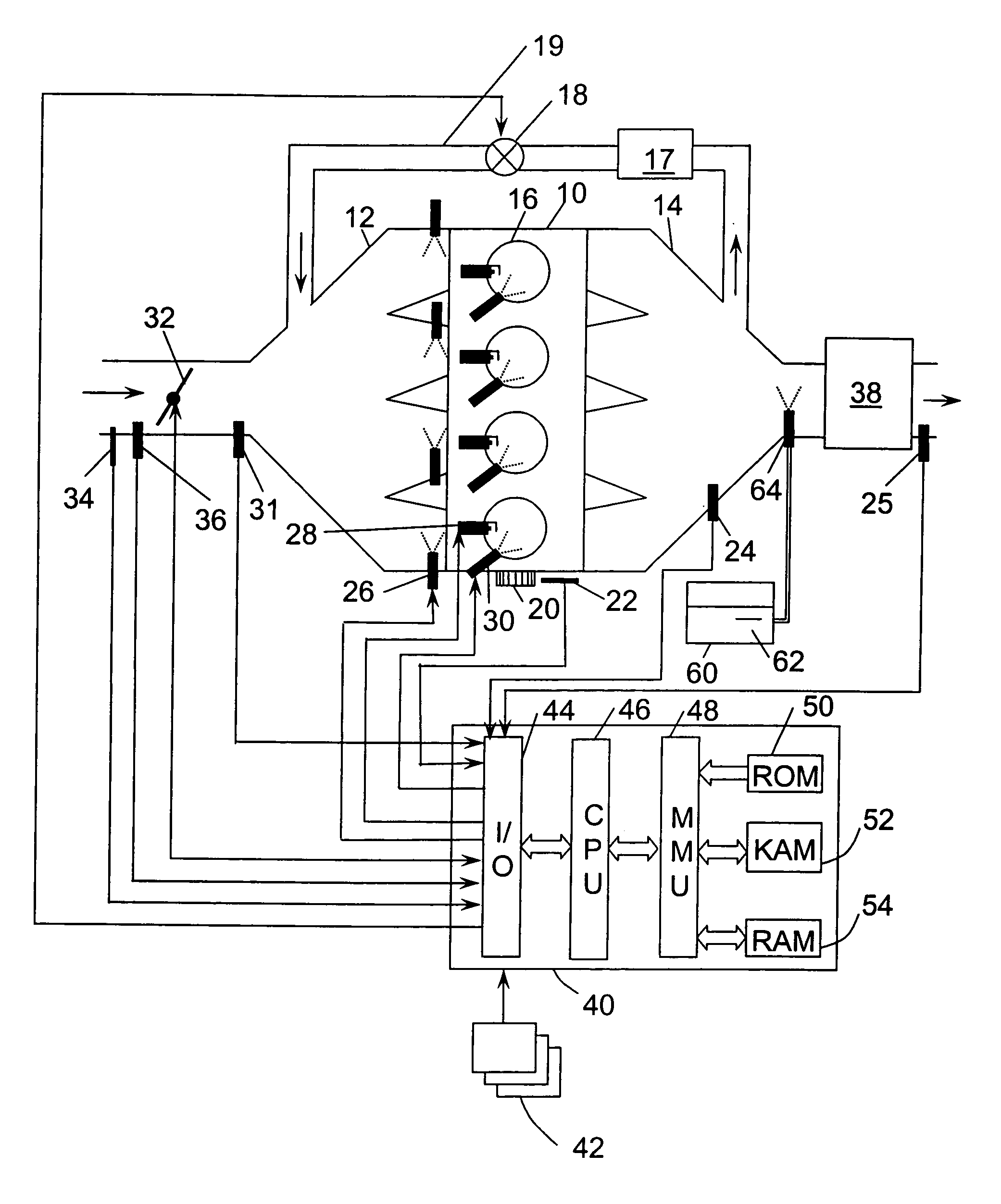
[0019] A 4-cylinder internal combustion engine 10 is shown, by way of example, in FIG. 1. Engine 10 is supplied air through intake manifold 12 and discharges spent gases through exhaust manifold 14. An intake duct upstream of the intake manifold 12 contains a throttle valve 32 which, when actuated, controls the amount of airflow to engine 10. Sensors 34 and 36 installed in intake manifold 12 measure air temperature and mass air flow (MAF), respectively. Sensor 31, located in intake manifold 14 downstream of throttle valve 32, is a manifold absolute pressure (MAP) sensor. A partially closed throttle valve 32 causes a pressure depression in intake manifold 12. When a pressure depression exists in intake manifold 12, exhaust gases are caused to flow through exhaust gas recirculation (EGR) duct 19, which connects exhaust manifold 14 to intake manifold 12. Within EGR duct 19 is EGR valve 18, which is actuated to control EGR flow and optional intercooler 17. Fuel is supplied to engine 10 ...


PUM

PropertyMeasurementUnit
Porosityaaaaaaaaaa
Porosityaaaaaaaaaa
Porosityaaaaaaaaaa

Abstract

An exhaust aftertreatment device for an internal combustion engine is disclosed which contains multiple, parallel channels of a porous material, such as cordierite or silicon carbide, in which about some of the channels are plugged at an upstream end and other channels remain unplugged. In one embodiment, the substrate has an SCR coating and the engine has a urea supply system. Other embodiments include using TWC and LNT formulations. Several washcoat configurations and other specific geometries and dimensions to encourage crossflow, diffusion, and adsorption are disclosed herein.

Description

FIELD OF THE INVENTION [0001] The present invention relates to a device for treating exhaust gases from an internal combustion engine. In particular, the exhaust aftertreatment device contains parallel channels of a porous material with about half of the channels being plugged on the upstream end. The device is coated with a SCR (selective catalytic reduction) washcoat. BACKGROUND OF THE INVENTION [0002] Achieving low NOx (NO, nitric oxide, plus NO2, nitrogen dioxide) emissions from lean-burning engines, such as diesels is a challenge. To treat NOx emitted from diesel engines, SCRs and LNTs (lean NOx traps) have been developed. LNTs operate in a lean / rich cycle in which NOx is purged during lean operation and NOx is released and reacted in a shorter period of rich operation. A disadvantage of LNTs is that they significantly degrade diesel fuel economy. Although SCRs do not consume a large amount of extra fuel to react NOx, urea is supplied to the SCR to cause the NOx reaction. For v...

Claims


Application Information

Patent Timeline
IPC IPC(8): B01D50/00
CPCF01N3/0222F01N3/206F01N3/208Y10T29/49345F01N2610/02F01N2610/146Y02T10/24F01N2560/021Y02T10/12F01N3/02
Inventor WILLEY, RAY L.ZIMMERMAN, BRET A.KUBINSKI, DAVID J.BREHOB, DIANA D.
Owner FORD GLOBAL TECH LLC
Why Eureka
Try Eureka