High temperature component with thermal barrier coating and gas turbine using the same
a technology of thermal barrier coating and high temperature component, which is applied in the direction of machines/engines, climate sustainability, waterborne vessels, etc., can solve the problems of top coat spalling or damage, and the top coat is liable to be spat or damaged, so as to enhance the durability of the top coat
- Summary
- Abstract
- Description
- Claims
- Application Information
AI Technical Summary
Benefits of technology
Problems solved by technology
Method used
Image
Examples
example 1
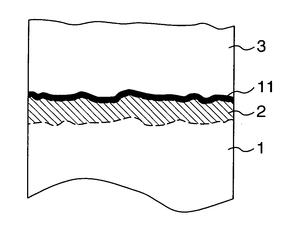
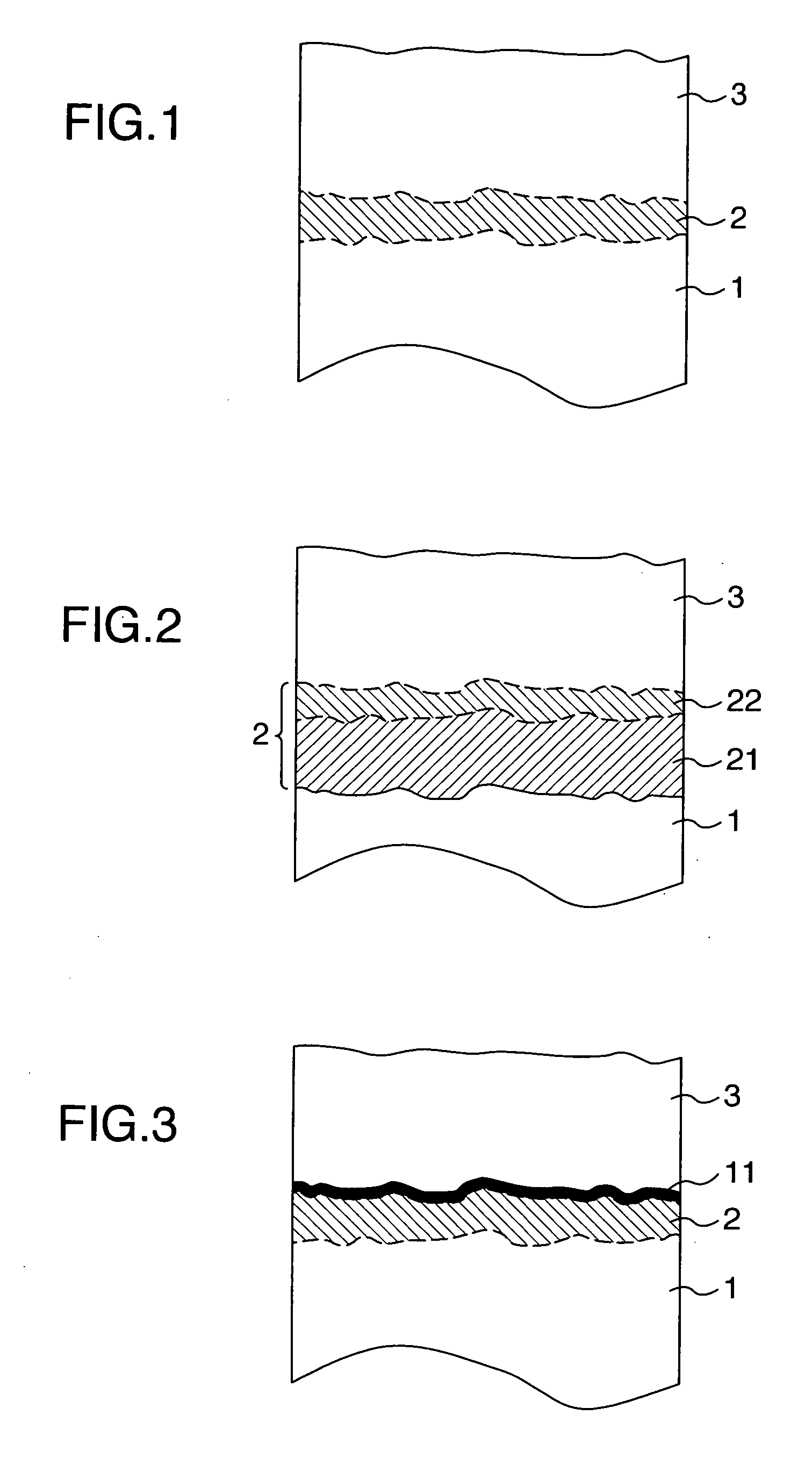
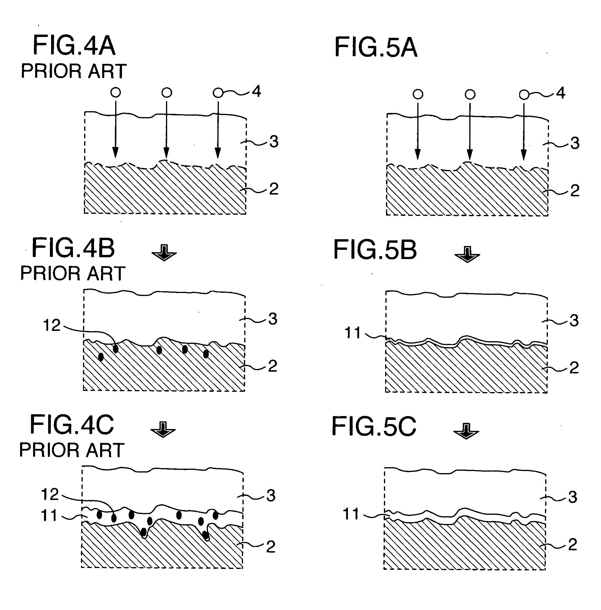
[0029] As a specimen for a substrate, a nickel-based super-alloy (IN738LC: Ni-16 wt % Cr-8.5 wt % Co-1.7 wt % Mo-2.6 wt % W-1.7wt % Ta-0.9 wt % Nb-3.4 wt % Al-3.4 wt % Ti') having a disc shape with a diameter of 25 mm and a thickness of 5 mm was used. A bond coat was formed on the substrate by a low-pressure plasma spray technique using CoNiCrAl alloy (Co-32 wt % Ni-21 wt % Cr-8 wt % Al) powder, and heat-treated at a temperature of 1121° C. for 4 hours under vacuum, as diffusion heat treatment. The thickness of the bond coat was about 100 μm. Subsequently, a top coat with a thickness of about 200 μm was formed onto the bond coat on the substrate by the atmospheric plasma spray technique using yttria partially stabilized zirconia (ZrO2-8 wt % Y2O3) powder.
[0030] To evaluate the effect for suppressing growth of the interface oxide according to the present invention, an atmospheric oxidation test was conducted at 950° C. for 1000 hours on the specimen prepared by the above-described m...
example 2
[0032] The same specimen for the substrate as that of Example 1 was used, and a bond coat was formed on the surface thereof by the low-pressure plasma spray technique using NiCoCrAl alloy (Ni-23 wt % Co-17 wt % Cr-12.5 wt % Al) powder. It was heat-treated at 1121° C. for 4 hours under vacuum, as diffusion heat treatment. The thickness of bond coat was about 100 μm. Subsequently, top coats of yttria partially stabilized zirconia (ZrO2-8 wt % Y2O3) were formed onto the bond coat on the substrate by the following four methods so as to have a thickness of about 200 μm.
[0033] A first method: a top coat having a porosity of about 10% was formed by the atmospheric plasma spray technique.
[0034] A second method: a porous top coat having a porosity of about 20% was formed by the atmospheric plasma spray technique.
[0035] A third method: a top coat having a vertical crack was formed by the atmospheric plasma spray technique.
[0036] A fourth method: a top coat having a columnar structure was ...
example 3
[0039] The same specimen for the substrate as that of Example 1 was used, and a bond coat was formed by the low-pressure plasma spray technique. The bond coat was formed so as to have a two-layer structure. For a first layer on the substrate side, a CoNiCrAlY alloy (Co-32 wt % Ni-21 wt % Cr-8 wt % Al-0.5 wt % Y) was formed so as to have a thickness of about 100 μm, and for a second layer, a CoNiCrAl alloy (Co-32 wt % Ni-21 wt % Cr-8 wt % Al) was formed so as to have a thickness of about 50 μm. Subsequently, it was heat-treated at 1121° C. for 4 hours under vacuum, as diffusion heat treatment. Thereafter, a top coat with a thickness of about 200 μm and a diameter of 15 mm was formed at the center of the specimen by the atmospheric plasma spray technique using yttria partially stabilized zirconia (ZrO2-8 wt % Y2O3) powder with using a metallic mask. A specimen was also prepared in which the bond coat was formed as a single layer with a thickness of about 150 μm made of a CoNiCrAl allo...
PUM
| Property | Measurement | Unit |
|---|---|---|
| temperature | aaaaa | aaaaa |
| temperature | aaaaa | aaaaa |
| thickness | aaaaa | aaaaa |
Abstract
Description
Claims
Application Information
 - R&D
- Intellectual Property
- Life Sciences
- Materials
- Tech Scout
- Unparalleled Data Quality
- Higher Quality Content
- 60% Fewer Hallucinations
Browse by: Latest US Patents, China's latest patents, Technical Efficacy Thesaurus, Application Domain, Technology Topic, Popular Technical Reports.
© 2025 PatSnap. All rights reserved.Legal|Privacy policy|Modern Slavery Act Transparency Statement|Sitemap|About US| Contact US: help@patsnap.com


