Configurations and methods of carbon capture

a carbon capture and carbon capture technology, applied in the field of acid gas removal, can solve the problems of increasing the energy consumption of the plant, all or almost all of these processes are expensive and energy-inefficient, and the process remains relatively expensiv

Inactive Publication Date: 2006-11-23
FLUOR TECHSE CORP
View PDF7 Cites 52 Cited by
  • Summary
  • Abstract
  • Description
  • Claims
  • Application Information

AI Technical Summary

Problems solved by technology

However, since venting carbon dioxide into the atmosphere is now believed to have a negative impact on the earth's climate, various attempts have been made to remove carbon dioxide from the flue gas of IGCC and other plants.
However, all or almost all of these processes tend to be expensive and energy inefficient due to the relatively low carbon dioxide partial pressures in the flue gas.
However, separating H2S and COS from the synthesis gas still requires a liquid solvent, from which CO2 is removed by stripping the solvent with nitrogen.
Consequently, such processes still remain relatively expensive, especially due to the solvent regeneration.
While use of solid phase adsorbents is generally less expensive or environmentally problematic than solvent based absorption, regeneration of solid phase adsorbents typically requires heating in a temperature swing operation, thereby significantly increasing energy consumption of the plant.
Consequently, although various configurations and methods for carbon dioxide removal are known in the art, all or almost all of them suffer from one or more disadvantages.

Method used


Image

  • Configurations and methods of carbon capture
  • Configurations and methods of carbon capture
  • Configurations and methods of carbon capture

Examples


Embodiment Construction

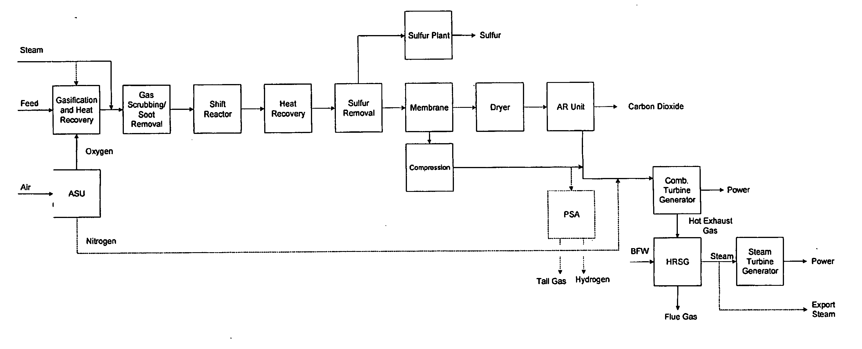
[0023] The inventors discovered that acid gases, and especially sulfur compounds and carbon dioxide can be effectively removed from a feed gas using autorefrigeration before the feed gas is combusted. Contemplated configurations advantageously reduce emission of pollutants that otherwise would have to be removed from flue gases at relatively low concentrations and pressure, thereby providing a more cost and energy efficient solution for decarbonization. In preferred configurations, the feed gas is IGCC syngas and the decarbonization is operationally coupled to sulfur removal from the feed gas before combustion of the processed syngas.

[0024] In a further preferred aspect of the inventive subject matter, syngas is conventionally formed using one or more gasification or partial oxidation units (typically using steam and oxygen), all of which are well known in the art. For example, suitable gasification reactors may include a reaction zone and a quench zone as described in U.S. Pat. No...


PUM

PropertyMeasurementUnit
pressureaaaaaaaaaa
temperaturesaaaaaaaaaa
pressureaaaaaaaaaa

Abstract

An IGCC plant has a precombustion decarbonization unit in which acid gas is removed from a combustion gas before the combustion gas enters a combustion turbine. In one preferred configuration, a sulfur removal unit removes hydrogen sulfide from a feed gas before the desulfurized feed gas enters an autorefrigeration unit in which carbon dioxide is removed. In another preferred configuration, hydrogen sulfide is converted to carbonyl sulfide in a dryer, and the carbonyl sulfide is absorbed in the liquid carbon dioxide that is prepared from the feed gas using autorefrigeration.

Description

[0001] This application claims the benefit of U.S. provisional patent application No. 60 / 460,363, filed Apr. 3, 2003, and which is incorporated by reference herein.FIELD OF THE INVENTION [0002] The field of the invention is acid gas removal from a feed gas, and especially removal of acid gases from syngas before syngas combustion (precombustion decarbonization). BACKGROUND OF THE INVENTION [0003] Gasification of various feeds is often integrated with a combined-cycle power unit to form an IGCC plant that typically exhibits relatively high efficiency for generation of electric power from relatively low-value carbonaceous feedstocks. The flue gas from the combustion turbine of such IGCC plants typically contains approximately 2-4% carbon dioxide, which has frequently been released into the atmosphere. However, since venting carbon dioxide into the atmosphere is now believed to have a negative impact on the earth's climate, various attempts have been made to remove carbon dioxide from ...

Claims


Application Information

Patent Timeline
Patent Type & Authority Applications(United States)
IPC IPC(8): C10J3/84F25J1/00B01DB01D1/00B01D53/14B01D53/26B01D53/40C01B3/52C01B32/50F25J3/02F25J3/04F25J3/06
CPCB01D53/002Y02E20/18B01D53/1493B01D53/526B01D2257/304B01D2257/308B01D2257/504C01B3/50C01B3/52C01B31/20C01B2203/02C01B2203/0283C01B2203/0405C01B2203/0415C01B2203/043C01B2203/0475C01B2203/0485C01B2203/0872C01B2203/84C01B2203/86C10J3/00C10J2300/165C10J2300/1675C10J2300/1678C10J2300/1687C10K1/002C10K1/004C10K1/02C10K1/101C10K1/16F25J3/0223F25J3/0252F25J3/0266F25J3/04545F25J3/04575F25J3/0625F25J3/0655F25J3/067F25J2205/30F25J2205/40F25J2205/80F25J2215/04F25J2220/82F25J2220/84F25J2240/02F25J2260/80F25J2270/12F25J2270/60Y02C10/06Y02C10/08Y02C10/12Y02E20/185B01D53/047C01B32/50Y02C20/40Y02P30/00Y02P20/151B01D53/8615
Inventor REDDY, SATISHVYAS, SUNILSCHERFFIUS, JEFFREY
Owner FLUOR TECHSE CORP
Why Eureka
Try Eureka