Reproduction method, optical disk drive, and IC circuit
a technology of optical disk drive and reproduction method, which is applied in the direction of digital signal error detection/correction, instruments, recording signal processing, etc., can solve the problems of low-performance drive, increased possibility of causing such a problem of reproduction compatibility, and reproducing error
- Summary
- Abstract
- Description
- Claims
- Application Information
AI Technical Summary
Benefits of technology
Problems solved by technology
Method used
Image
Examples
first embodiment
(Reproduction Method)
[0094] Experiment was carried out with an evaluator and a sample medium conforming to a 16×-speed DVD-RAM in order to examine the effectiveness of the aforementioned verification method of the present invention. The record was done at a 6×-speed, the reproduction was done by using the center track out of the five consecutive tracks while the reproduction speed and tilt conditions were changed, and jitter, PI error, the number of row error, the number of 2 T data, and others were measured.
[0095]FIG. 9 shows the actual measurement results of the relationship between tangential tilt and a jitter value. FIG. 10 shows the actual measurement results of the relationship between tangential tilt and PI error. The two binarization methods, the direct slice method and the PRML method, are compared with each other. It is understood that the PRML method shows higher performance. FIG. 11 shows the actual measurement results of the relationship between a read speed and a ji...
second embodiment
(Circuit)
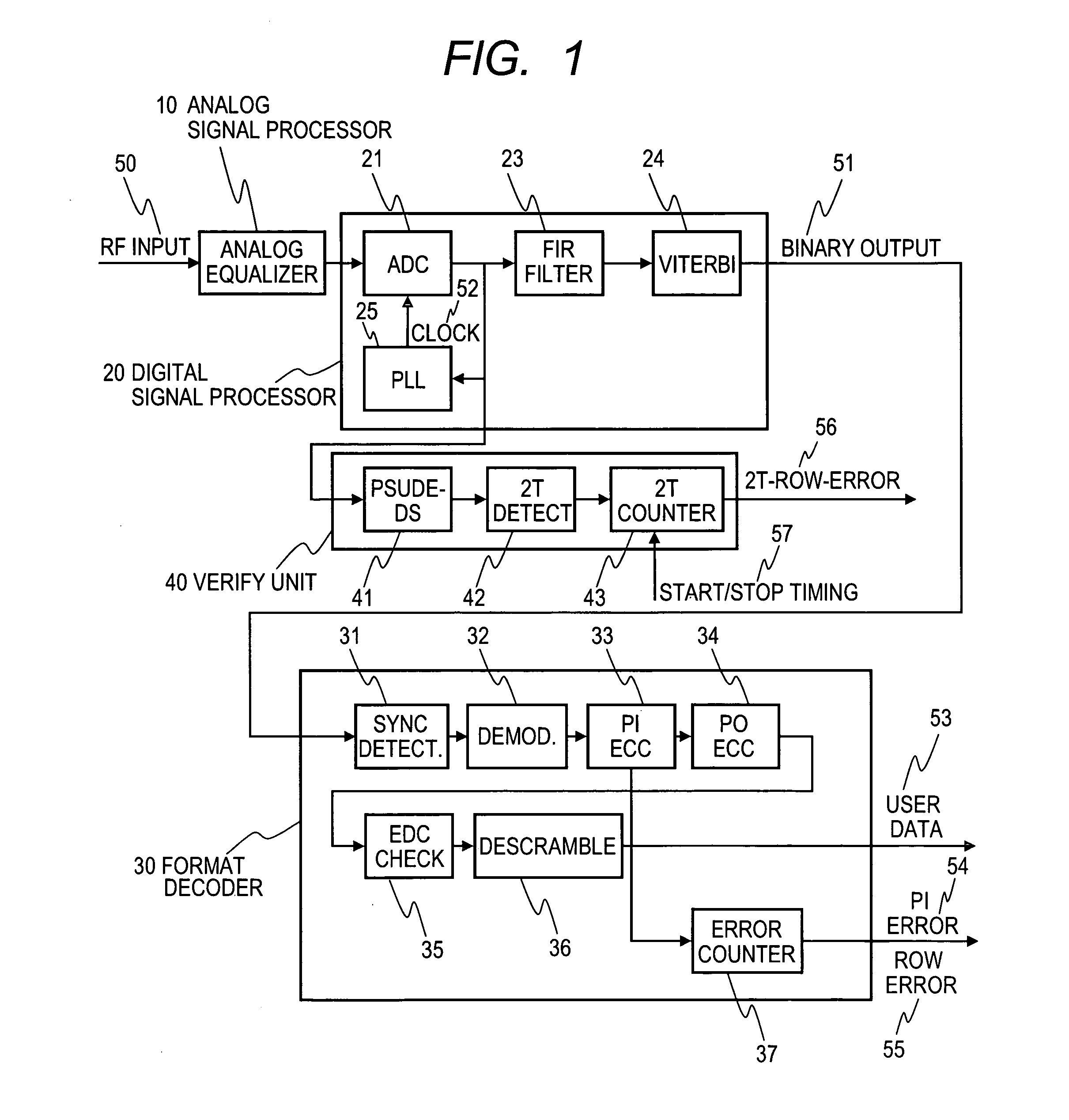
[0107] The configuration of a circuit suitable for the realization of an optical disk drive according to the present invention is hereunder explained on the basis of the drawings.
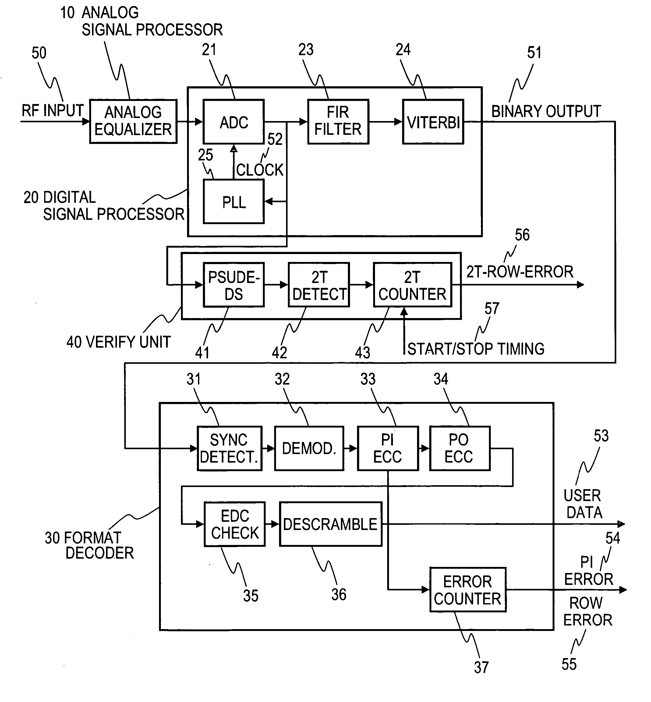
[0108]FIG. 1 is a block diagram showing a circuit configuration suitable for the implementation of the present invention. An RF signal 50 detected with an optical head not shown in the figure is subjected to equalization processing, AGC processing and others with an analog signal processor 10 and thereafter input into a digital signal processor 20. In the digital signal processor 20, the input RF signal is: converted into a digital signal for each clock with an AD converter 21; thereafter digitally equalized with an FIR filter 23; binarized with a Viterbi decoder 24; and ejected as a binarized signal 51. The internal structure of the Viterbi decoder 24 is not described here in detail because it exceeds the scope of the present invention but, just briefly, the Viterbi decoder 24 is a device to co...
third embodiment
(Optical Disk Drive)
[0145]FIG. 42 is a view schematically showing an example of the configuration of an optical disk drive according to the present invention. An optical disk medium 100 is driven by a motor 160. At the time of reproduction, a laser power / pulse controller 120 controls the current supplied to a semiconductor laser 112 in an optical head 110 so that a light intensity directed by a CPU 140 can be secured and laser beam 114 is generated. The laser beam 114 is focused with an objective lens 111 and forms a light spot 101 on the optical disk medium 100. The reflected light 115 from the light spot 101 is detected with a photo-detector 113 through the objective lens 111. The photo-detector comprises a plurality of divided light-detecting components. A readout signal processor 130 reproduces information recorded on the optical disk medium 100 with the signal detected with the optical head 110. At the time of record, the laser power / pulse controller 120 converts prescribed r...
PUM
 Abstract
Description
Claims
Application Information
 - R&D
- Intellectual Property
- Life Sciences
- Materials
- Tech Scout
- Unparalleled Data Quality
- Higher Quality Content
- 60% Fewer Hallucinations
Browse by: Latest US Patents, China's latest patents, Technical Efficacy Thesaurus, Application Domain, Technology Topic, Popular Technical Reports.
© 2025 PatSnap. All rights reserved.Legal|Privacy policy|Modern Slavery Act Transparency Statement|Sitemap|About US| Contact US: help@patsnap.com


